
Underground tool providing on-line information for in situ assessment of aquifer quality and flow rate

a technology of in situ assessment and online information, applied in the field of assessment of aquifer reservoirs, can solve the problems of affecting the marketing value of products, the collection mechanism involved has not undergone many changes, and the time consumption is excessive,

Active Publication Date: 2019-04-18
AQUARESOURCES SA +1
View PDF4 Cites 7 Cited by
  • Summary
  • Abstract
  • Description
  • Claims
  • Application Information

AI Technical Summary

Benefits of technology

The patent text suggests adding two supplements to the rear shoe to increase its fixation diameter in large diameter wells. The technical effect of this is better attachment of the shoe to the well casing, which improves the stability and reliability of the well.

Problems solved by technology

However, in spite of such evolution, the aquifer identification systems that assess water quality and quantity, as well as the collection mechanisms involved have not undergone many changes.
In the present situation it is necessary to find irrigation water whose characteristics define it as suitable for its intended use, and this not only takes time but also sometimes involves excessive costs that affect the marketing values of products.
Strain gauges have a better dynamic response since they reach a stable measurement value faster than quartz gauges but they are not as accurate in measuring as the latter, which outperform them as regards resolution and accuracy, but require a long stabilization period when there are sudden pressure and temperature variations inside the well.

Method used


Image

  • Underground tool providing on-line information for in situ assessment of aquifer quality and flow rate
  • Underground tool providing on-line information for in situ assessment of aquifer quality and flow rate
  • Underground tool providing on-line information for in situ assessment of aquifer quality and flow rate

Examples


Embodiment Construction

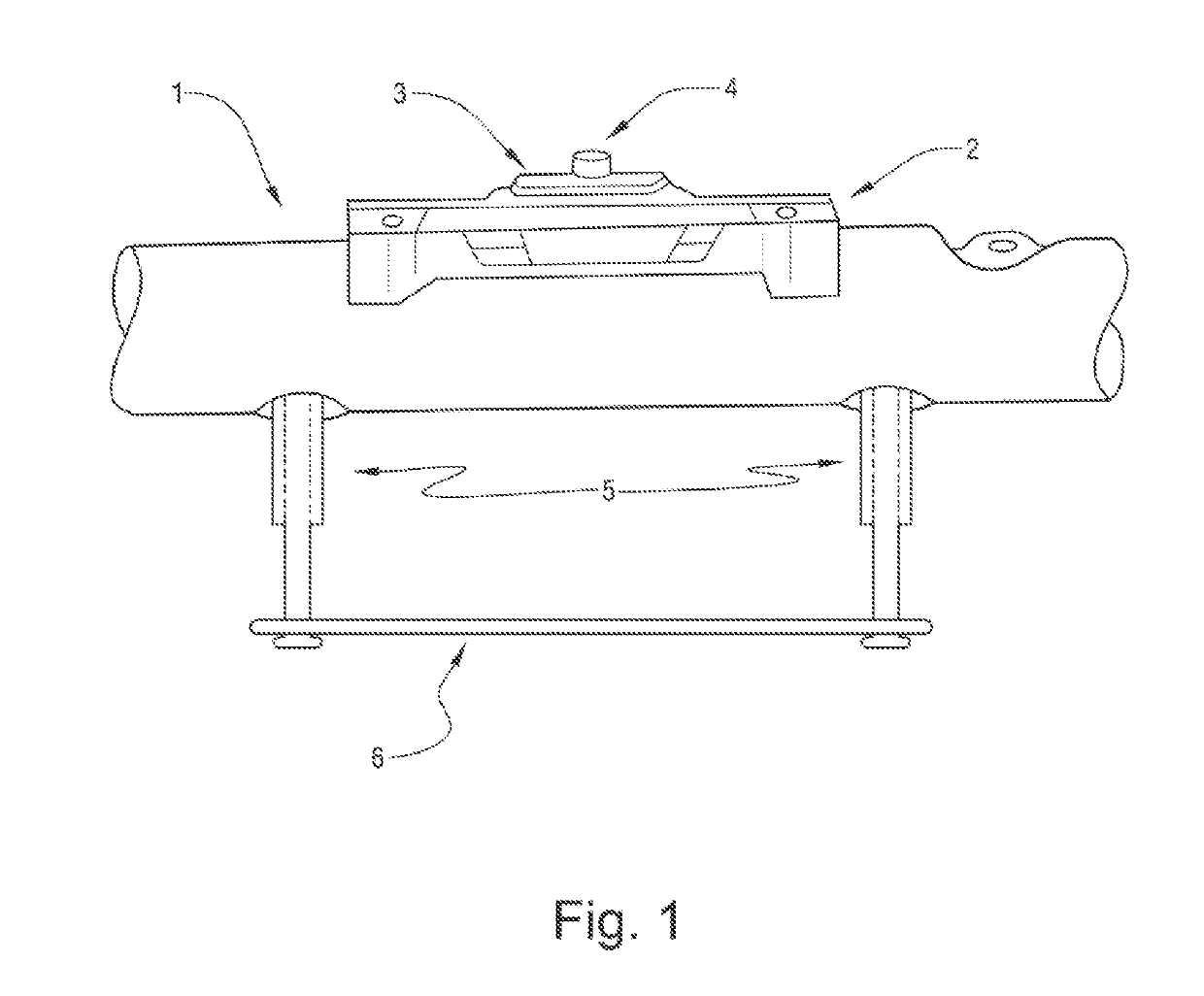
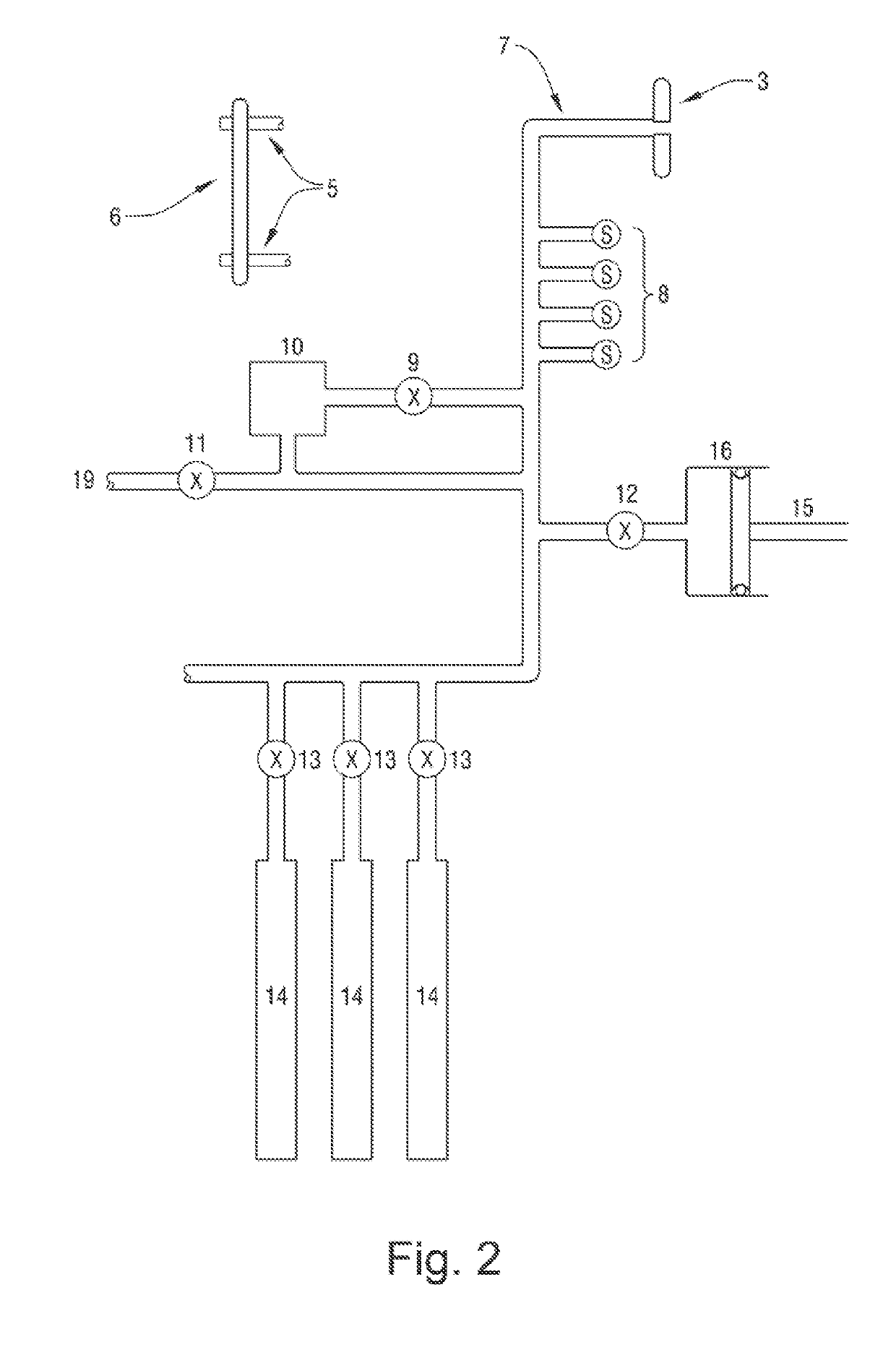
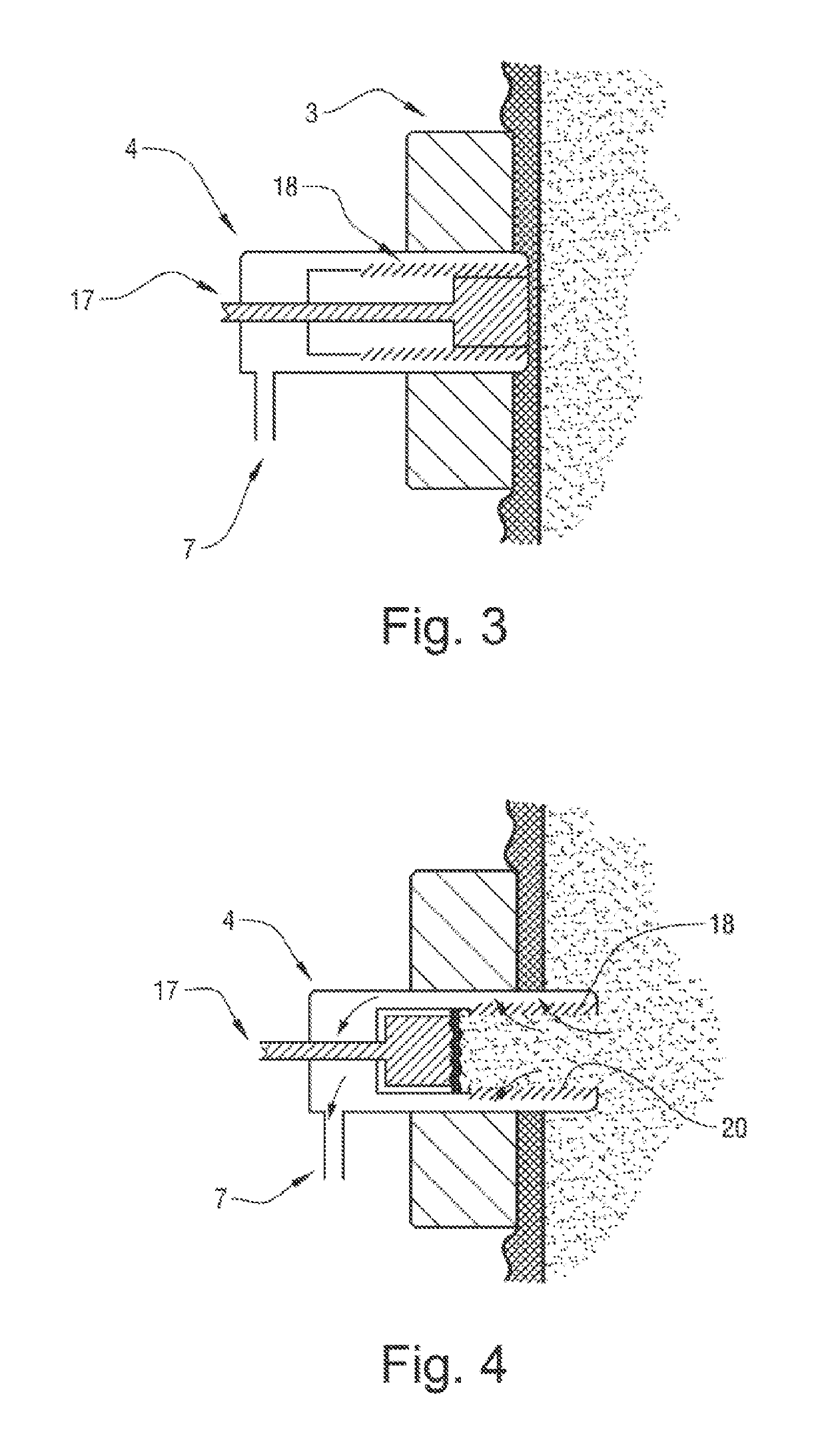
[0116]It is, therefore, a primary object of the present invention, to provide an underground sampling tool (HTMS) (1) for obtaining on-line information on the quality and flow rate of underground aquifers in the search for uncontaminated water for crop irrigation, which is designed to extract liquids impregnating the subterranean formations that are reached by drilling, and analyzing them in situ.

[0117]The HTMS (1) of FIG. 1 according to the present invention includes for its basic operation all the elements of a modern tool as regards the means for attaching it to the borehole walls.

[0118]A rear shoe (6) on an axial axis of the tool, which can be called 180° axis to differentiate it from the rear shoe (6), attached to two telescopic pistons (5) simultaneously from the inside and outside driven by a signal of a surface equipment operatively enabled for this purpose (as shown in FIG. 1).

[0119]A front shoe (2), on the 0° axial axis opposite to the rear shoe (6), on the 180° axial axis...


PUM

PropertyMeasurementUnit
volumeaaaaaaaaaa
volumeaaaaaaaaaa
pressureaaaaaaaaaa

Abstract

An underground sampling tool (HTMS) for underground water analysis of both quality and flow rate, providing the information required to perform an underground drilling and obtain uncontaminated water for crop irrigation, said tool comprising: a housing for the electronic and electrical controls, a housing for the hydraulic means controlled by the electric and electronic portion of the tool, a test body consisting of a variety of hydraulic circuits for operating the various operating valves of the tool, wherein said test body further comprises: a rear shoe on an axial axis of the tool, wherein said rear shoe is driven by two telescoping pistons simultaneously that arise from the inside of the tool when driven by a signal of a surface equipment operably enabled for this purpose, and a front shoe, driven by several pistons which are housed below the front shoe, not shown in the figures, and driven by one or more electro-pneumatic devices acting jointly and generating a progressive forward or backward movement of the front shoe. Process for the collection and analysis of samples in a wellbore using said tool.

Description

TECHNICAL FIELD[0001]The present invention relates to the assessment of aquifer reservoirs intended for use in agriculture, more particularly to devices and methods used to measure in situ the qualitative and quantitative values required to determine whether a reservoir is suitable for agriculture.BACKGROUND[0002]Hunting, fishing, agriculture, and the different ways of taming nature, have been essential for the development of communities.[0003]The ancient industry of agriculture has strongly influenced all civilizations in their strive to feed their growing population.[0004]Crops and their production have undergone a qualitative and quantitative leap during the twentieth century as never before in history, mainly as a result of the evolution of three fields of technology:[0005]1—biotechnology[0006]2—agricultural techniques[0007]3—phytosanitation and fertilizers[0008]The first milestone occurred during the 1920s, when the first hybrid materials were obtained in maize crops, by crossi...

Claims


Application Information

Patent Timeline
Patent Type & Authority Applications(United States)
IPC IPC(8): E21B49/10E21B47/06E21B47/10G01N1/20
CPCE21B49/10E21B47/06E21B47/065E21B47/10G01N1/2042E21B2049/085E02D1/027E02D1/06E21B49/08G01N1/14G01N1/2035E21B47/07E21B49/0875
Inventor MORGAN, ENRIQUE JUAN
Owner AQUARESOURCES SA
Learn More