
Tracheostoma valve

a tracheostoma valve and valve body technology, applied in the direction of tracheal tubes, respirators, etc., can solve the problems of inferior lung capacity or need of respiratory treatment, inability to obtain enough air, and inability to achieve normal nasal function

Active Publication Date: 2019-04-18
COLOPLAST AS
View PDF0 Cites 1 Cited by
  • Summary
  • Abstract
  • Description
  • Claims
  • Application Information

AI Technical Summary

Benefits of technology

The present invention provides a tracheostoma device for use with a tracheostoma device holder. The device comprises a tubular body and a container for housing a heat and moisture exchanging foam. The device is designed to alleviate or eliminate symptoms associated with tracheostoma for individuals with breathing difficulties. The device has a hardness of less than or equal to 100 Shore A. The technical effects of this invention include improved respiratory function, reduced symptoms associated with breathing difficulties, and improved quality of life for individuals with tracheostoma.

Problems solved by technology

A tracheostomy is performed for example when there is a malfunction, such as a result from injury or disorder, in respect of the nervous system or the respiratory passages, which malfunction results in an incapacity to obtain enough air.
An inferior lung capacity or need of respiratory treatment may also result in a tracheostomy.
After this procedure, normal nasal function is not possible.
A disadvantage with this device holder is that the tracheostoma aid device will be released once a retaining force threshold is overcome by exhaled air pressure.
Also, the sealing effect between the tracheostoma device holder and the tracheostoma aid device will also be affected by the retaining force threshold, such that the risk of unwanted air leakage between the tracheostoma device holder and the tracheostoma aid device is increased, which will negatively affect the possibility to control for example air flow through a voice prosthesis in the oesophagal / tracheal wall.
When removing the tracheostoma device it is then also necessary to overcome the very same frictional force, which simultaneously must ensure sealing and retention, which means that these two parameters both must be taken into account—meaning that one of them cannot be maximized since it would hamper the other.

Method used


Image

  • Tracheostoma valve
  • Tracheostoma valve
  • Tracheostoma valve

Examples


Embodiment Construction

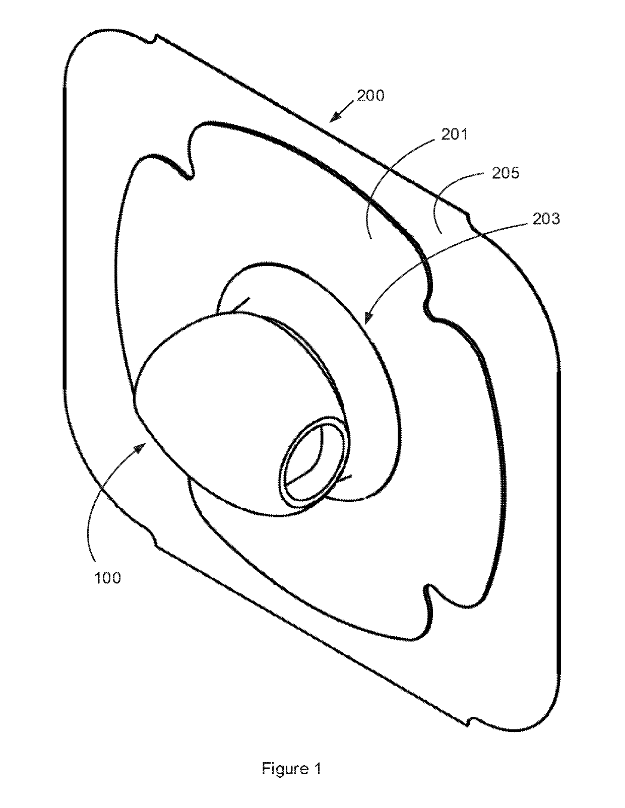
[0022]The following description focuses on an embodiment of the present invention applicable to a tracheostoma device 100, for being held in a tracheostoma device holder 200 over the stoma of a person. A tracheostoma device 100 may in this context be a tracheostoma valve, HME, speech valve, etc., or combinations thereof.

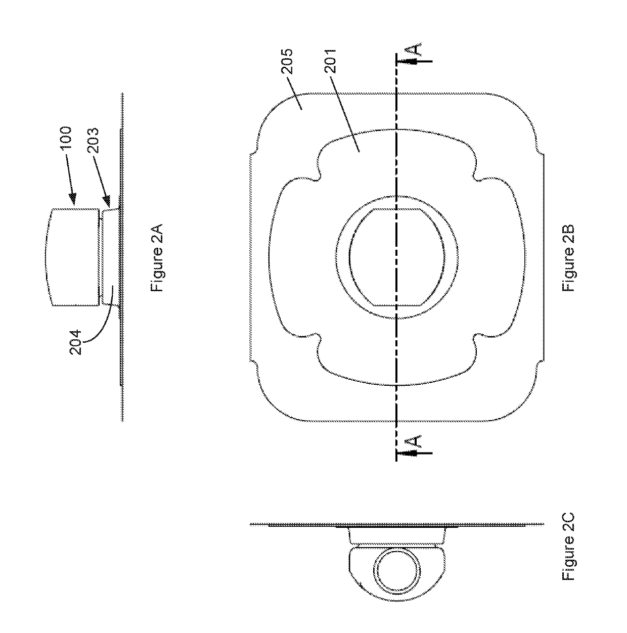
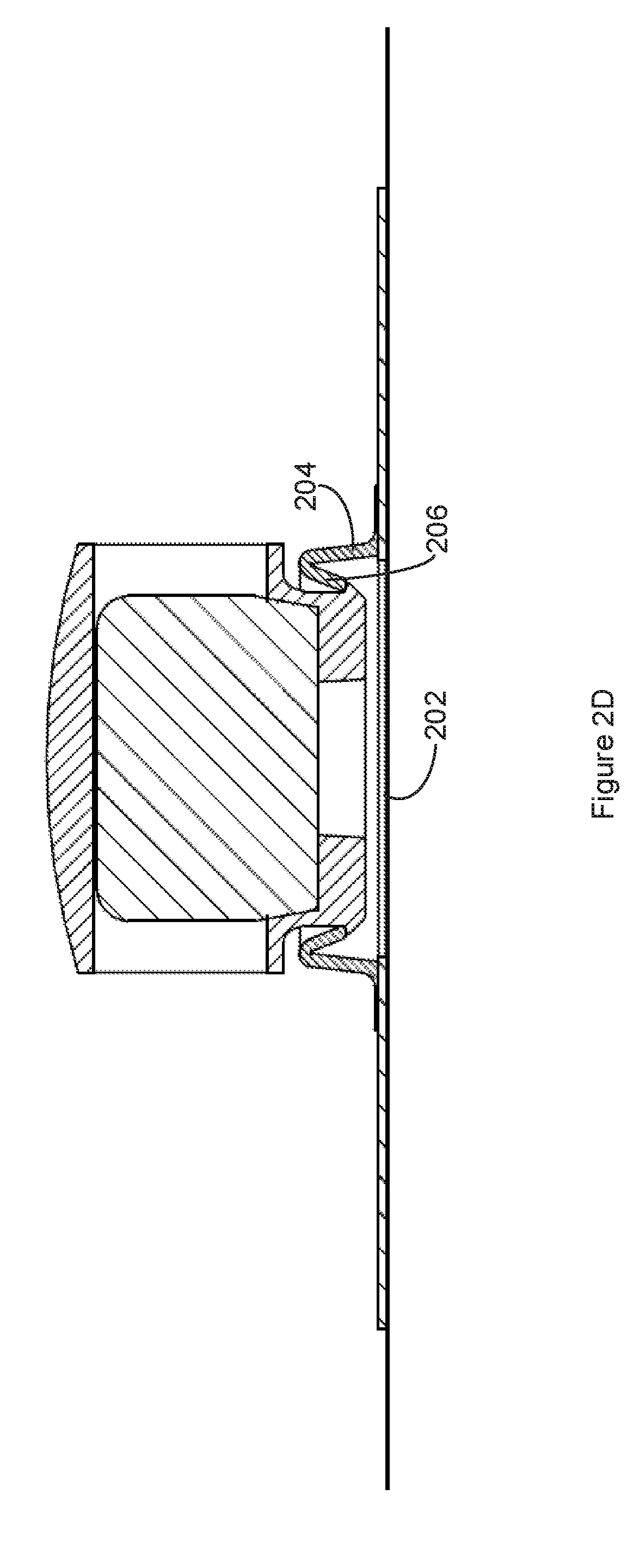
[0023]FIGS. 1 to 4 illustrate a tracheostoma device 100 for being held in a tracheostoma device holder 200, superimposed of a tracheostoma of a person, is disclosed. The tracheostoma device holder 200 comprises a skirt 201 for attachment over a tracheostoma via a skin adhesive proximal side thereof. The skirt 201 is preferably flexible. The skirt 201 is provided with a through hole 202. The tracheostoma device holder 200 also comprises a tubular tracheostoma device fitting 203. The tubular tracheostoma device fitting 203 is arranged circumferentially of the through hole 202. The tubular tracheostoma device fitting 203 extends distally from the distal side of the skir...


PUM


Abstract

A tracheostoma device for cooperation with a tracheostoma device holder superimposed on a tracheostoma of a person is provided. The tracheostoma device comprises a tubular body and a container. Said tubular being at the proximal end of the tracheostoma device, comprising at least one inlet upon exhalation through the tracheostoma device, and being adapted for cooperation with the tracheostoma device holder. The container being at the distal end of the tracheostoma device, comprising at least one outlet upon exhalation through the tracheostoma device, and being adapted for housing a heat and moisture exchanging foam. The tubular body and the container may have a hardness of less than and including 100 Shore A.

Description

FIELD OF THE INVENTION[0001]This invention pertains in general to a tracheostoma device. More particularly, the present invention pertains to a tracheostoma device to be connected to a tracheostoma device holder, said tracheostoma device holder comprising a skirt for attachment over a tracheostoma via the proximal side of the skirt, said skirt being provided with a through hole having a tubular tracheostoma device fitting extending distally from the skirt circumferentially of said through hole.BACKGROUND OF THE INVENTION[0002]A tracheostomy is a surgical procedure in which an opening is formed through the anterior surface of the neck into the trachea. The opening is referred to as a tracheostoma. A tracheostomy tube can be provided to extend between the tracheostoma and the trachea. A tracheostomy is performed for example when there is a malfunction, such as a result from injury or disorder, in respect of the nervous system or the respiratory passages, which malfunction results in a...

Claims


Application Information

Patent Timeline
IPC IPC(8): A61M16/04A61M16/10
CPCA61M16/0468A61M16/1045A61M16/047
Inventor SELVEO, THOMASMAGNUSSON, RONNYALFREDSSON, MARCUS
Owner COLOPLAST AS
Learn More