
Electronic device comprising antenna

a technology of electronic devices and antennas, applied in the direction of resonant antennas, substantially flat resonant elements, high frequency circuit adaptations, etc., can solve the problems of reducing the radiation performance of the antenna, reducing or preventing power leakage, and reducing or eliminating the influence of a transmission line. , the effect of improving the radiation performance of the electronic devi

Active Publication Date: 2019-03-07
SAMSUNG ELECTRONICS CO LTD
View PDF0 Cites 8 Cited by
  • Summary
  • Abstract
  • Description
  • Claims
  • Application Information

AI Technical Summary

Benefits of technology

The patent text discusses the issue of power leakage in electronic devices caused by the overlap of the antenna and display. The technical effect of this patent is to provide an electronic device that reduces or eliminates power leakage by eliminating or reducing the influence of the transmission line and shield layer on the display. This results in improved radiation performance and overall user experience.

Problems solved by technology

Power leakage may occur due to a transmission line generated according to the above condition, and radiation performance of the antenna may be reduced.

Method used


Image

  • Electronic device comprising antenna
  • Electronic device comprising antenna
  • Electronic device comprising antenna

Examples


Embodiment Construction

[0035]Embodiments of the disclosure will be described herein below with reference to the accompanying drawings. However, the embodiments of the disclosure are not limited to the specific embodiments and should be construed as including all modifications, changes, equivalent devices and methods, and / or alternative embodiments of the present disclosure. In the description of the drawings, similar reference numerals are used for similar elements.

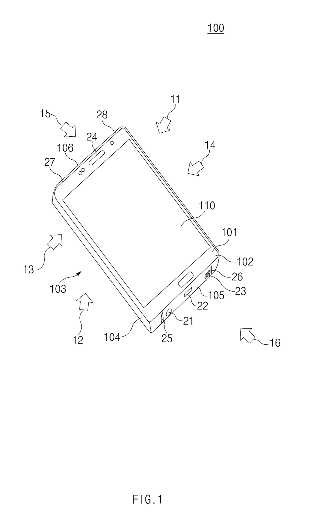
[0036]FIG. 1 is a diagram of an electronic device, according to an embodiment.

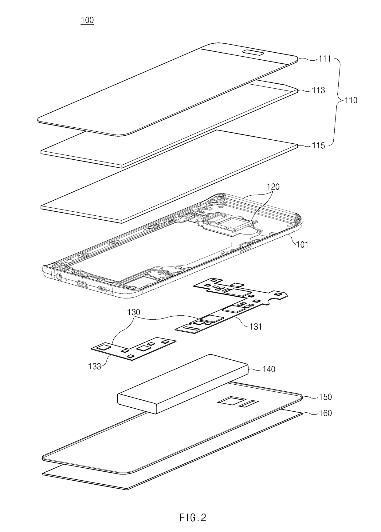
[0037]An electronic device 100 may include a housing 101 and a display 110. Various circuits or modules such as a processor, a memory, and the like may be positioned within the electronic device 100 (i.e., within the housing 101).

[0038]The housing 101 may form at least a portion of the exterior of the electronic device 100. The housing 101 may include a first plate 102 (e.g., a front plate) facing in an upper direction (e.g., a first direction) 11 and a second plate 1...


PUM


Abstract

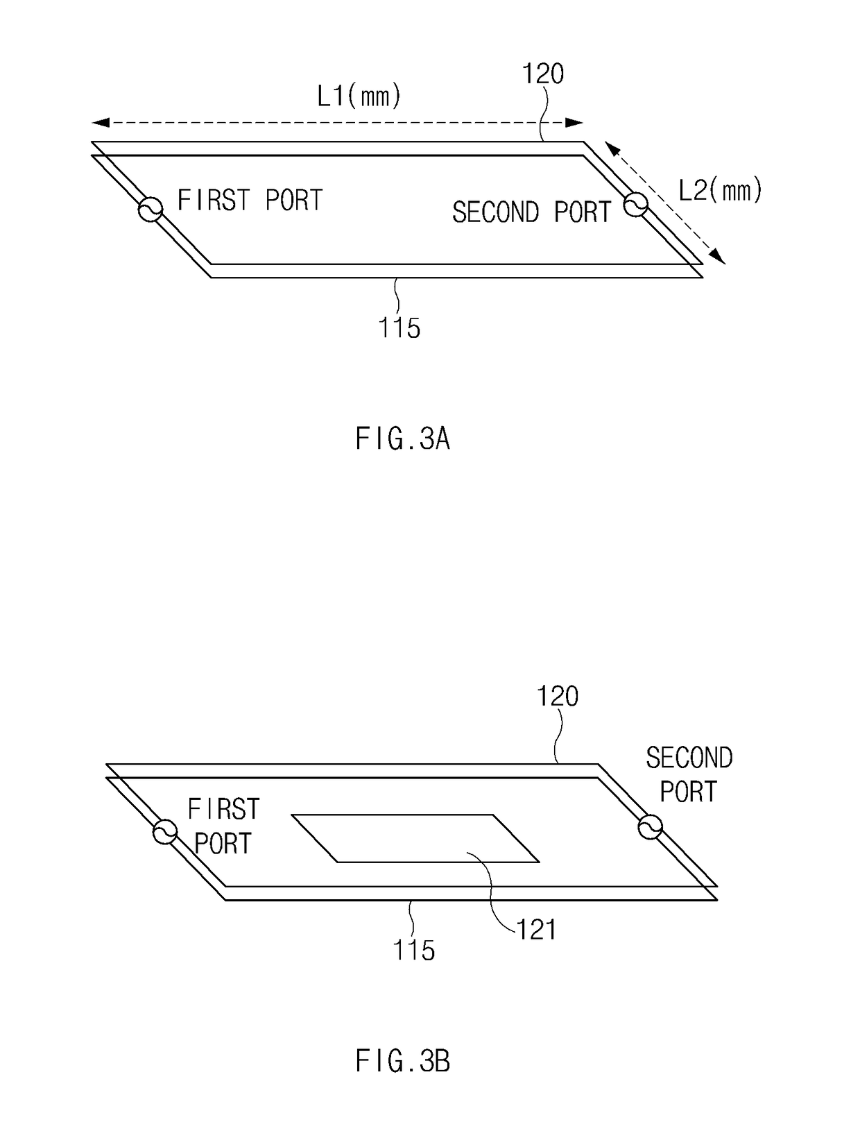
An electronic device is provided. The electronic device includes a housing including a front plate, a rear plate facing away from the front plate, and a side member surrounding a space between the front plate and the rear plate, the housing including at least one antenna element extended along one portion of the side member, a display exposed through the front plate and including a display panel and a shield layer, a wireless communication circuit electrically connected to the antenna element, a support member, at least a portion of which is positioned in the space in parallel with the shield layer, and a conductive patch layer interposed between the shield layer and the support member.

Description

CROSS-REFERENCE TO RELATED APPLICATION(S)[0001]This application is based on and claims priority under 35 U.S.C. § 119 to Korean Patent Application Serial No. 10-2017-0114626, filed on Sep. 7, 2017, in the Korean Intellectual Property Office, the entire disclosure of which is incorporated herein by reference.BACKGROUND1. Field[0002]The present disclosure relates generally to an electronic device and more particularly, to an electronic device including a technology associated with performance of an antenna.2. Description of Related Art[0003]An electronic device, which is equipped with a display, such as a smartphone, a wearable device, or the like has been widely supplied as mobile communication technologies develop. The electronic device may execute various functions, such as a photo or video capturing function, a music or video file play function, a game function, an Internet function, and the like, through the display.[0004]Currently, a technology for maximally enlarging the size o...

Claims


Application Information

Patent Timeline
Patent Type & Authority Applications(United States)
IPC IPC(8): H01Q1/24H01Q1/38H01Q13/10H04M1/02H05K1/02H01Q1/52H01Q9/04
CPCH01Q1/243H01Q1/38H01Q13/10H04M1/0266H05K1/0237H01Q1/526H01Q9/0407H05K1/0216H04M1/0262H04M1/0249H04M1/0277
Inventor BAE, HONG PYOKIM, DONG YEONNAM, HO JUNGPARK, SUNG KOOPARK, JAE WOONSEO, MIN CHEOLYUN, HIM CHANLEE, HAN DUGLEE, HYUN WOOLEE, HYUNG JOOLIM, BYUNG MANCHOI, NAK CHUNG
Owner SAMSUNG ELECTRONICS CO LTD
Learn More