Composite seal ring
a sealing ring and composite technology, applied in the direction of engines, mechanical equipment, machines/engines, etc., can solve the problems of insufficient rigidity at high temperature, seal ring breakage or valve lock, and decrease of sealing surface pressure with passage portions, etc., to achieve the effect of reducing resin rigidity and reducing tension
- Summary
- Abstract
- Description
- Claims
- Application Information
AI Technical Summary
Benefits of technology
Problems solved by technology
Method used
Image

Examples
first embodiment
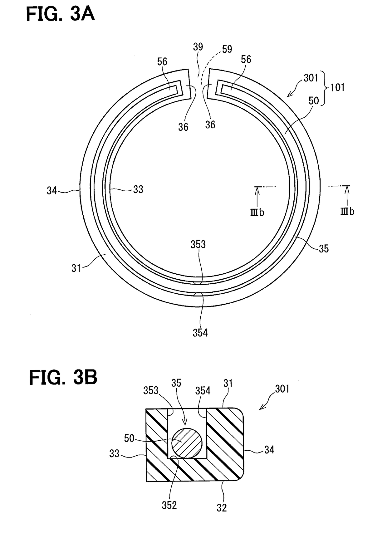
[0049]With reference to FIG. 3A and FIG. 3B, the configuration of the composite seal ring 101 of the first embodiment will be described. In the composite seal ring 101 in the first embodiment, a spring 50 is accommodated in a spring groove 35 formed in one axial end surface 31 of the seal ring 301.
[0050]The cross section in an axial direction of the seal ring 301 is a substantially rectangular shape surrounded by one end surface 31, the other end surface 32, the inner circumferential surface 33, and the outer circumferential surface 34 in the axial direction, and the spring groove 35 is formed on one end surface 31. The spring groove 35 has a groove bottom wall 352, a radially inner groove inner wall 353, and a radially outer groove inner wall 354, and is formed so as to be able to house the spring 50. The spring 50 is housed in the spring groove 35 so as to be annularly arranged within the radial width of the seal ring 301.
[0051]In addition, the seal ring 301 has a fitting opening ...
second embodiment
[0070]The second embodiment is explained with reference to FIG. 6A and FIG. 6B.
[0071]In the composite seal ring 102 of the second embodiment, the circumferential end walls 36 are not formed at both circumferential end portions of the seal ring 302 with respect to the first embodiment. Therefore, the spring 50 is freely movable in the circumferential direction. FIG. 6A shows a state in which the fitting opening 59 of the spring 50 and the fitting opening 39 of the seal ring 302 are arranged at a same position, and FIG. 6B shows a state in which the fitting 59 of the spring 50 and the fitting opening 39 of the seal ring 302 are arranged at different positions.
[0072]In the second embodiment, since the spring 50 can freely move, the stress caused by the collision between the spring 50 and the seal ring 302 is reduced.
third embodiment
[0073]The third embodiment is explained with reference to FIG. 7.
[0074]In the composite seal ring 103 of the third embodiment, a partition wall 37 is formed on the side opposite to the fitting opening 39 of the seal ring 303 in the circumferential direction. The spring 50 is accommodated in the spring groove 35 such that the partition wall 37 is interposed in the fitting opening 59. Therefore, the fitting opening 39 of the seal ring 303 faces the portion of the spring 50 which is opposite to the fitting opening 59.
[0075]In the third embodiment, since the relative movement of the spring 50 with respect to the seal ring 303 is suppressed as in the first embodiment, the abrasion of the seal ring 303 due to the sliding of the spring 50 is suppressed. Furthermore, since the fitting opening 39 of the seal ring 303 and the fitting opening 59 of the spring 50 are arranged at the different positions in the circumferential direction, the deformation of the composite seal ring 103 as a whole i...
PUM
 Abstract
Description
Claims
Application Information
 - R&D
- Intellectual Property
- Life Sciences
- Materials
- Tech Scout
- Unparalleled Data Quality
- Higher Quality Content
- 60% Fewer Hallucinations
Browse by: Latest US Patents, China's latest patents, Technical Efficacy Thesaurus, Application Domain, Technology Topic, Popular Technical Reports.
© 2025 PatSnap. All rights reserved.Legal|Privacy policy|Modern Slavery Act Transparency Statement|Sitemap|About US| Contact US: help@patsnap.com