
Vision guided robot path programming

a robot path and vision technology, applied in the field of vision guided robot path programming, can solve the problems of degrading the economics of robot use, degrading the use efficiency of robots, time-consuming and costly, etc., and achieve the effect of removing human involvemen

Active Publication Date: 2019-02-14
BRACHIUM
View PDF0 Cites 13 Cited by
  • Summary
  • Abstract
  • Description
  • Claims
  • Application Information

AI Technical Summary

Benefits of technology

The present invention is a system and method that allows a robot to teach itself by comparing a live image of a workspace with a reference image of a similar workspace. This process eliminates human involvement and allows the robot to program itself. The invention also monitors its progress along the path and modifies it to conform to the desired path. The technical effects of this invention include: 1) the ability to teach a robot without human guidance; 2) the ability to program a robot path for different objects with similar geometries, sizes, and process activation parameters; 3) the ability to automate the robot path programming process; 4) the ability to operate autonomously without human augmentation; and 5) the opportunity for robots to operate in new and uncertainties environments.

Problems solved by technology

This is time consuming and costly given the expense of the required skilled manual labor, and the need for many programming operations every time the workpiece or its location is changed.
Programs may consume several hours of skilled labor time and result in degrading the economics of robot use.
In addition the programming task requires investment in expensive training for operators.
These prior art methods are time consuming, costly, labor intensive, require high technical skills, require extensive computer processing operations, depend on human judgement for accurate location, require re-programming for each change of the environment and frequent iterative corrections.
If the actual site is displaced or deformed, the path generated virtually does not represent the distorted or displaced site, and the robot will not trace the desired path.
They increase robot initial cost for the added programming tools and user interface hardware, and they increase operating cost of automation with robots.

Method used


Image

  • Vision guided robot path programming
  • Vision guided robot path programming
  • Vision guided robot path programming

Examples


Embodiment Construction

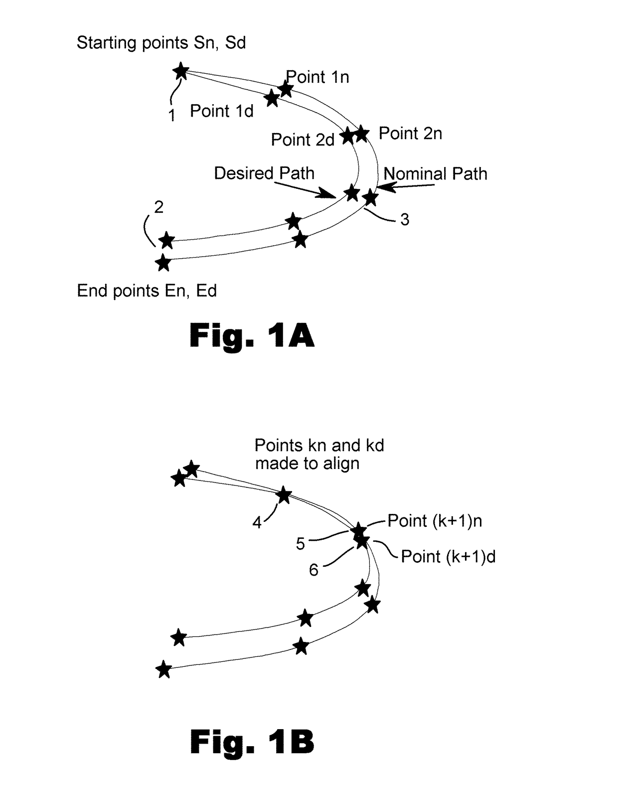
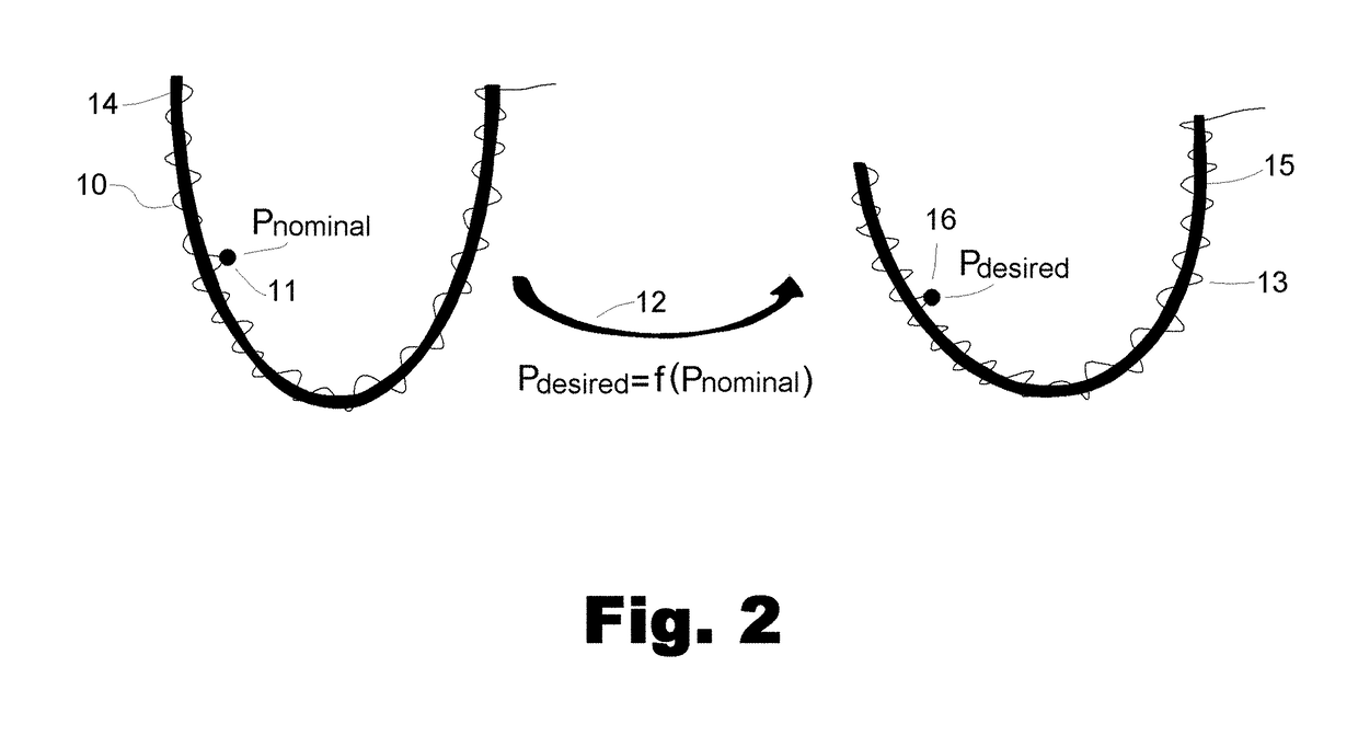
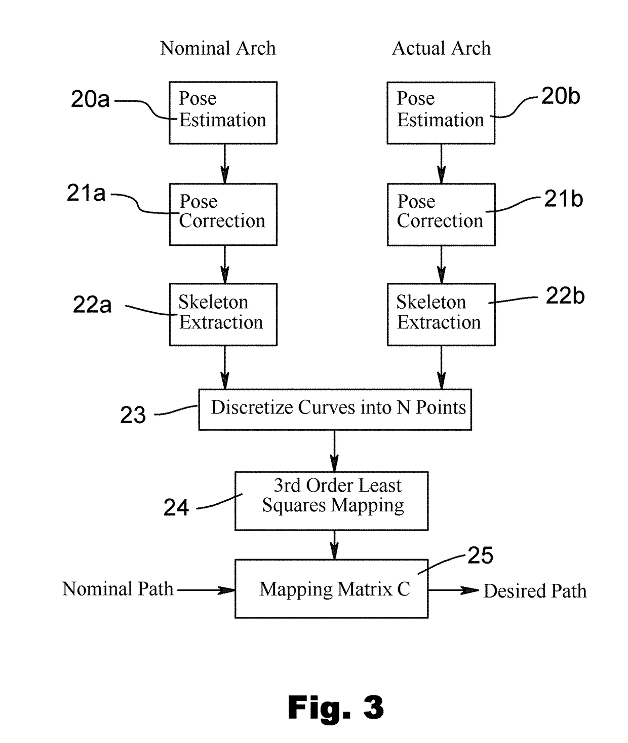
[0029]Embodiments of the present invention provide a system and method for programming the robot path to be traced on a physical target by the use of sensors, especially vision sensors. They allow the robot to identify the target and generate the desired path once it has the opportunity to recognize a preselected starting point along the path. Using a vision camera mounted on, or close by, the robot, and a reference image of the target having a nominal path associated with the reference image and having a designated starting point, the robot interacts with the vision camera and compares the live image of the target to the reference image and selects a corresponding path starting point on the live image.

[0030]Once at the path starting point, the robot vision system superimposes the nominal path on the live image, matching their starting points and their geometric coordinate frames. The robot matches features associated with a first end point of a first segment of the nominal path wit...


PUM


Abstract

A method to automate the process of teaching by allowing the robot to compare a live image of the work space along the desired path with a reference image of a similar workspace associated with a nominal path approximating the desired path, the robot teaches itself by comparing the reference image to the live image and generating the desired path at the desired location, hence eliminating human involvement in the process with most of its shortcomings. The present invention also overcomes the problem of site displacement or distortion by monitoring its progress along the path by sensors and modifying the path to conform to the desired path.

Description

[0001]This application is related to, and claims priority from, U.S. Provisional patent application No. 62 / 415,737 filed Nov. 1, 2016. Application 62 / 415,737 is hereby incorporated by reference in its entirety.BACKGROUNDField of the Invention[0002]The present invention relates generally to the field of dental robotic scanning and more particularly vision guided robot path programming.Description of the Problem Solved[0003]There are several methods for programming a robot to trace a certain geometric path in space as it carries and operates a tool along its path and executes some processing operations; the following are common approaches:[0004]Teach pendant programming: The robot is commanded by means of a hand-held device, a teach pendant, to move to desired points along the path and to trigger a process tool at selected points along the path such as gripping an article, spraying paint, operating a welding gun and the like. The teach pendant moves the robot arm by sending jogging co...

Claims


Application Information

Patent Timeline
IPC IPC(8): B25J9/16
CPCB25J9/1666B25J9/1697B25J9/163G05B2219/40499
Inventor AKEEL, HADIFAN, YONGXIANG
Owner BRACHIUM
Learn More