
Battery module having a plurality of battery cells, method for the production thereof, and battery

a battery module and battery cell technology, applied in the field of batteries, can solve the problems of deformation of the battery cell housing, inability to maintain individual battery cells, and inability to achieve the effect of discharging less efficiently

Active Publication Date: 2019-02-07
ROBERT BOSCH GMBH
View PDF0 Cites 1 Cited by
  • Summary
  • Abstract
  • Description
  • Claims
  • Application Information

AI Technical Summary

Benefits of technology

The patent describes a battery module with multiple battery cells and a method of producing it. The module has the advantage of being able to provide different levels of pressure to each cell, which allows for individual cells to age at different rates and even out over time. By adjusting the pressure, the module can compensate for the different temperatures and rates of aging of the cells. The module is designed with partition walls between the cells in a prismatic arrangement, which ensures that the pressure is transmitted effectively. Additionally, the patent explains how the module can be adjusted to compensate for inhomogeneous aging caused by different temperature distributions. Overall, the patent provides a solution for creating a battery module with uniform pressure and temperature control for each cell.

Problems solved by technology

Aging processes as a result of charging and discharging procedures in the individual battery cells produce internal forces that not only result in the individual battery cells not remaining in a constant shape for the duration of their serviceable life but also these processes, which are described as bulging, deform the housing of the battery cells.
The battery cells of a battery module comprise an inhomogeneous temperature distribution, wherein battery cells in the middle of a battery module are at a higher temperature as a result of the less efficient possibility of dissipating heat in comparison to the battery cells that are located on the edge of a battery module.

Method used


Image

  • Battery module having a plurality of battery cells, method for the production thereof, and battery

Examples


Embodiment Construction

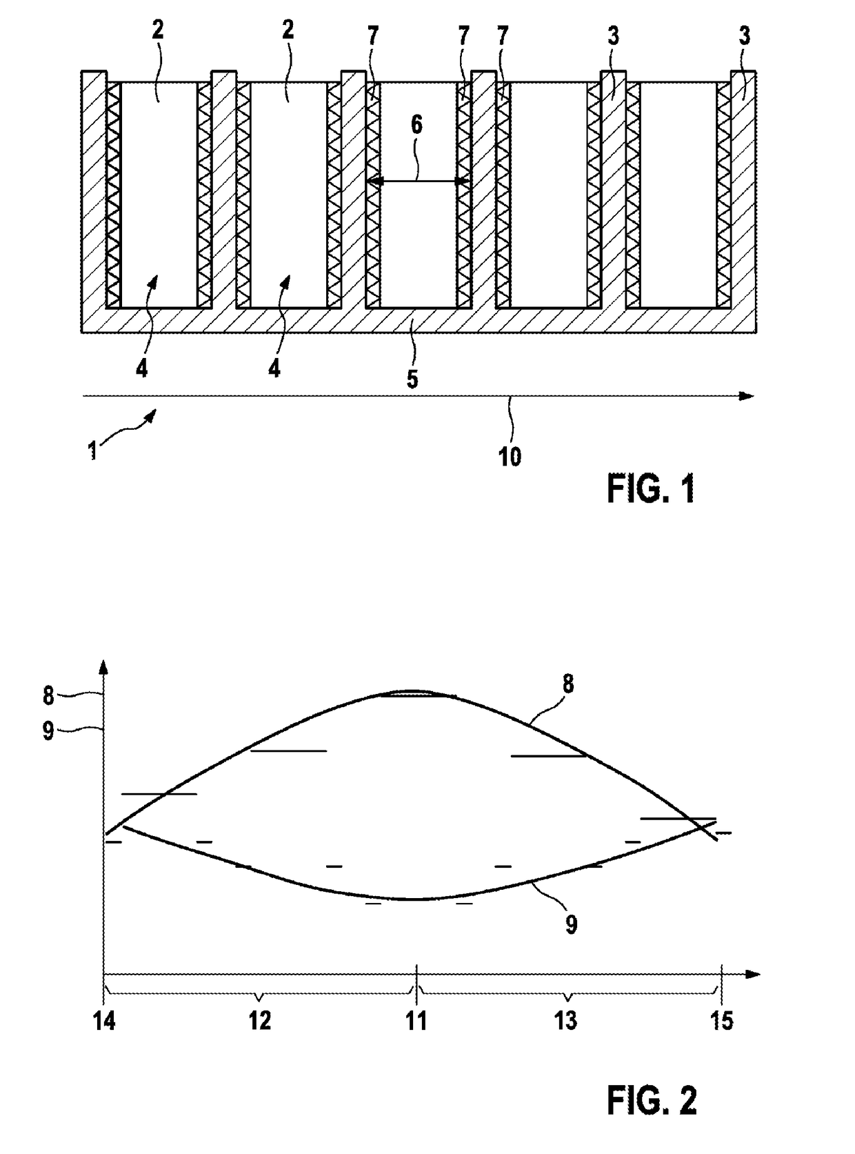
[0027]FIG. 1 illustrates schematically a side view of an embodiment of a battery module 1 in accordance with the invention.

[0028]The battery module 1 comprises a plurality of battery cells 2, wherein the battery module 1 illustrated in FIG. 1 comprises in particular five battery cells 2. Furthermore, the battery module 1 also comprises a plurality of partition walls 3 that, as is apparent in FIG. 1, are arranged between respectively two battery cells 2. As a consequence, a partition wall 3 is adjacent to two battery cells 2. The battery module 1 comprises furthermore two end-side partition walls 3 that may also be described as end plates. The end-side partition walls 3 or end plates are arranged respectively only adjacent to a battery cell 2 and therefore also, as is apparent in FIG. 1, are not arranged between respective two battery cells 2.

[0029]In the case of the battery module 1 that is illustrated in FIG. 1, the battery module 1 forms a plurality of receiving chambers 4, wherei...


PUM

PropertyMeasurementUnit
forceaaaaaaaaaa
elastic modulusaaaaaaaaaa
surface pressure modulusaaaaaaaaaa

Abstract

The invention relates to a battery module having a plurality of battery cells, in particular lithium ion battery cells, comprising a plurality of separating walls (3), wherein a battery cell (2) is arranged between two separating walls (3) and a first compensating element (7) is arranged between a first battery cell (2) and a separating wall (3) adjacent to the first battery cell (2) and a second compensating element (7) is arranged between a second battery cell (2) and a separating wall (3) adjacent to the second battery cell (2), characterized in that the first compensating element (7) and the second compensating element (7) have a different value (9) of a deformation constant.

Description

BACKGROUND OF THE INVENTION[0001]The invention relates to a battery module having a plurality of battery cells and a method for producing said battery module. A battery having such a battery module is also subject matter of the present invention.[0002]It is known from the prior art that batteries, such as in particular lithium ion batteries, comprise at least one battery module or advantageously also comprise a plurality of battery modules. Furthermore, it is preferred that a battery module comprises in addition a multiplicity of individual battery cells that are connected to one another to form the battery module. The individual battery cells may be connected to one another in series or in parallel.[0003]Aging processes as a result of charging and discharging procedures in the individual battery cells produce internal forces that not only result in the individual battery cells not remaining in a constant shape for the duration of their serviceable life but also these processes, whi...

Claims


Application Information

Patent Timeline
Patent Type & Authority Applications(United States)
IPC IPC(8): H01M2/10H01M10/04H01M10/0525H01M10/647H01M50/209
CPCH01M2/1077H01M10/04H01M10/0525H01M2/1061H01M10/647H01M10/0481Y02E60/10H01M50/209Y02P70/50
Inventor RIEDMANN, MATTHIASKOHN, PETERHAFENBRAK, ROBERTGREINER, DANIEL BERNDWAGNER, CHRISTIAN
Owner ROBERT BOSCH GMBH
Learn More