Higher harmonic control augmented with active vibration control

a vibration control and harmonic control technology, applied in the field of vibration control or suppression system in rotary wing aircraft, can solve the problems of airframe vibration, reduced payload of aircraft, and the inability of rotor-based systems to completely suppress all of the vibration loads originating from the main rotor(s)

Active Publication Date: 2019-01-24
SIKORSKY AIRCRAFT CORP
View PDF5 Cites 5 Cited by
  • Summary
  • Abstract
  • Description
  • Claims
  • Application Information

AI Technical Summary

Benefits of technology

[0025]FIG. 4 is a perspective view of an exemplary upper and lower rotor control system according to an embodiment of the invention;
[0026]FIG. 5 is a block diagram of the forces, moments, and control loads available for Higher Harmonic Control (HHC) of a dual, counter-rotating, coaxial rotor system; and
[0027]FIG. 6 is a schematic diagram of an Active Vibration Control (AVC) system and a HHC control system for a dual, counter-rotating, coaxial rotor system according to an embodiment.

Problems solved by technology

Forces and moments are transmitted through the gearbox into the airframe, resulting in airframe vibration.
Active vibration control (AVC) systems that are characterized by anti-vibration actuators mounted in the fuselage or on or very near the helicopter main transmission to suppress otherwise high levels of vibration are often heavier than desirable, resulting in a reduced payload of the aircraft.
In general, rotor-based systems cannot totally suppress all of the vibratory loads originating from the main rotor(s) either because the number of distinct load directions is greater than the number of controls or because the power or amplitude needed to provide complete suppression of the vibration by the rotor-based system alone is onerous.
As a result, the residual vibration may thus “leak” into the airframe and cause unwanted vibration.

Method used


Image

  • Higher harmonic control augmented with active vibration control
  • Higher harmonic control augmented with active vibration control
  • Higher harmonic control augmented with active vibration control

Examples


Embodiment Construction

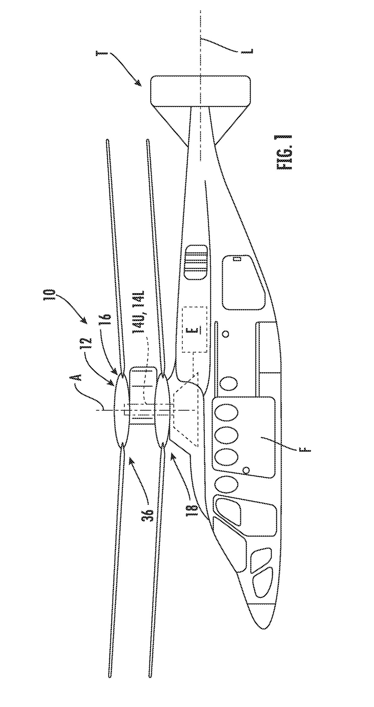
[0029]FIG. 1 illustrates an exemplary vertical takeoff and landing (VTOL) rotary wing aircraft 10 having a dual, counter-rotating main rotor system 12, which rotates about a rotating upper main rotor shaft 14U, and a counter-rotating lower main rotor shaft 14L (FIGS. 1 and 2), both about an axis of rotation A. The aircraft 10 includes an airframe F which supports the dual, counter-rotating, coaxial main rotor system 12 as well as an optional translational thrust system T which provides translational thrust during high speed forward flight, generally parallel to an aircraft longitudinal axis L. Although a particular counter-rotating, coaxial rotor system aircraft configuration is illustrated in the disclosed embodiment, other rotor systems and other aircraft types such as tilt-wing and tilt-rotor aircrafts will also benefit from the present invention.

[0030]A main gearbox G (FIG. 2) located above the aircraft cabin drives the rotor system 12. The translational thrust system T may be d...


PUM


Abstract

A rotary wing aircraft includes a rotor system rotatable about an axis relative to an airframe. A plurality of blade assemblies is mounted to the rotor system. A higher harmonic control system is operable to generate a harmonic load at the rotor system according to a higher harmonic control signal. An active vibration control system is operable to generate vibration forces about the aircraft according to an active vibration control signal. A controller is operable to issue the higher harmonic control signal and the active vibration control signal to coordinate the higher harmonic control system and the active vibration control system to reduce vibration within the airframe.

Description

CROSS-REFERENCE TO RELATED APPLICATIONS[0001]This application claims the benefit of U.S. Provisional Application Ser. No. 62 / 534,335, filed Jul. 19, 2017, which is incorporated herein by reference in its entirety.BACKGROUND OF THE INVENTION[0002]Exemplary embodiments of the invention generally relate to a rotary wing aircraft, and more particularly, to a vibration control or suppression system in a rotary wing aircraft.[0003]Rotary wing aircraft, or rotorcraft, can generate significant vibratory responses during operation. The primary source of such vibration is that generated by the main rotor system rotating at the blade passing frequency and the periodic loads acting on the rotor blades. Forces and moments are transmitted through the gearbox into the airframe, resulting in airframe vibration.[0004]Active vibration control (AVC) systems that are characterized by anti-vibration actuators mounted in the fuselage or on or very near the helicopter main transmission to suppress otherwi...

Claims


Application Information

Patent Timeline
Patent Type & Authority Applications(United States)
IPC IPC(8): B64C27/00B64C27/605B64C27/10
CPCB64C27/001B64C27/605B64C27/10B64C2027/004B64C27/72B64C2027/002B64C2027/003B64C2027/7238B64C2027/7244Y02T50/30
Inventor WELSH, WILLIAM A.SAHASRABUDHE, VINEET
Owner SIKORSKY AIRCRAFT CORP
Why Eureka
Try Eureka