Recording apparatus

a recording apparatus and recording technology, applied in the field of recording apparatuses, can solve the problems of degrading affecting the quality of recorded images, and affecting the user's hand,

Active Publication Date: 2019-01-17
SEIKO EPSON CORP
View PDF6 Cites 2 Cited by
  • Summary
  • Abstract
  • Description
  • Claims
  • Application Information

AI Technical Summary

Benefits of technology

[0024]According to this eighth configuration, when a voltage is applied to the conductive member, an electric field is generated between the conductive member and the second conductive member. The eighth configuration, therefore, reduces the risk that the mist is adhered onto the recording head.

Problems solved by technology

In the case where the mist is adhered on the ink cartridge, there is a risk that, when a user replaces the ink cartridge, the mist may soil the user's hand.
Further, in the case where the mist is adhered on a nozzle forming face of the recording head, there is a risk that a defect may occur in the ejection of the ink, and the defect may degrade the quality of recorded images.
As a result, there is a risk that misalignments among the landing positions of the ink droplets may occur, and such misalignments may degrade the quality of recorded images.
On the contrary, when the electrode plate is not strongly charged, a situation where the collection of the mist is insufficient may occur.
For this reason, it has been difficult to apply, to the electrode plate, a high voltage enough to effectively collect a large amount of mist that arises in the discarding regions for the discarded, ejected ink at the time of the execution of the borderless recording.

Method used


Image

  • Recording apparatus
  • Recording apparatus
  • Recording apparatus

Examples


first embodiment

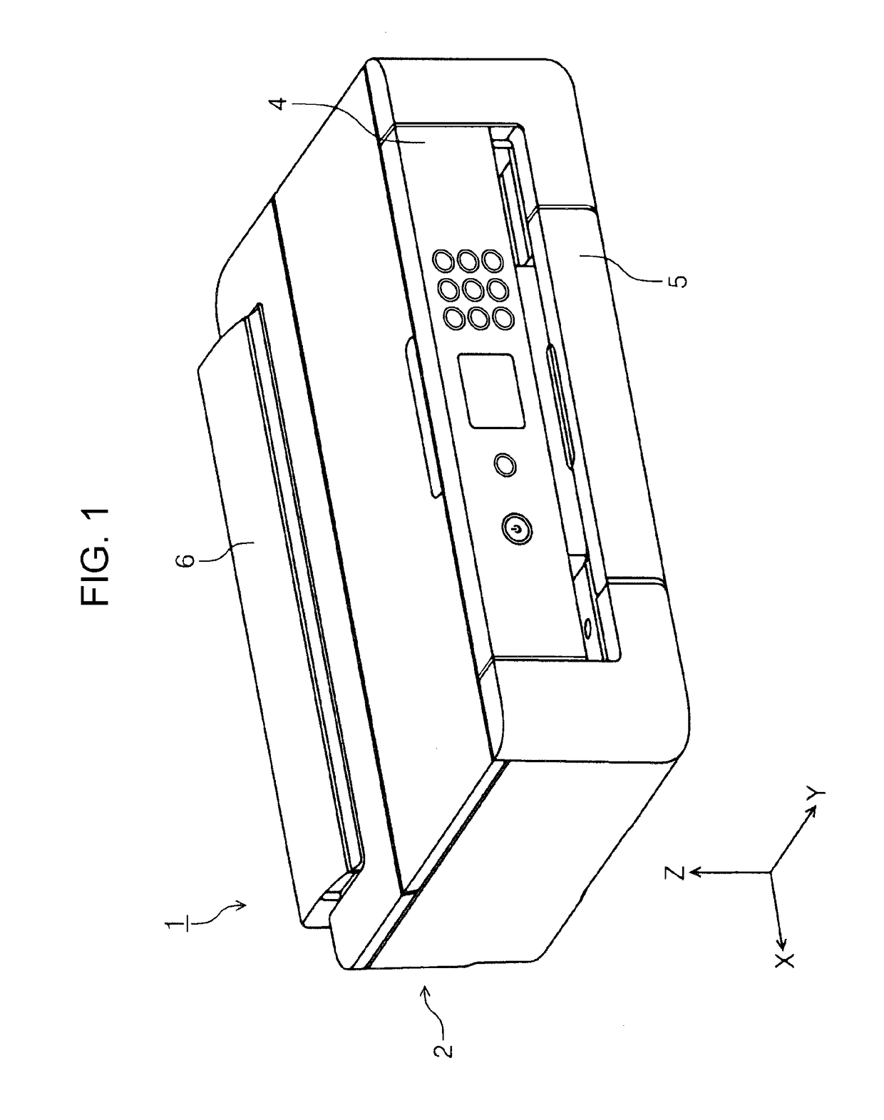
[0043]First, the outline of a recording apparatus according to an embodiment of the invention will be described. In the present embodiment, an ink jet printer 1 will be exemplified as an example of the recording apparatus. The ink jet printer 1 will be referred to as just a printer 1 hereinafter.

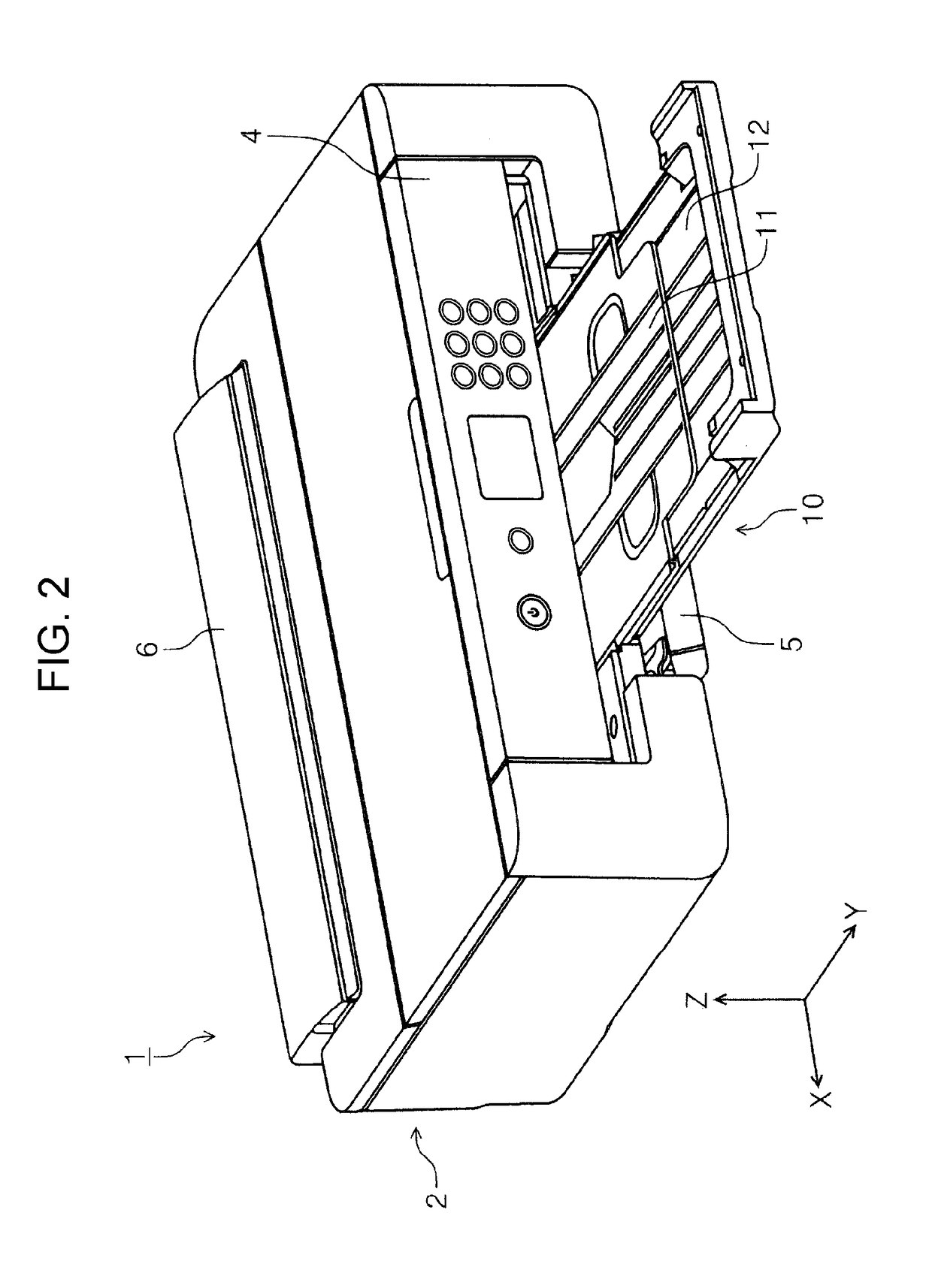
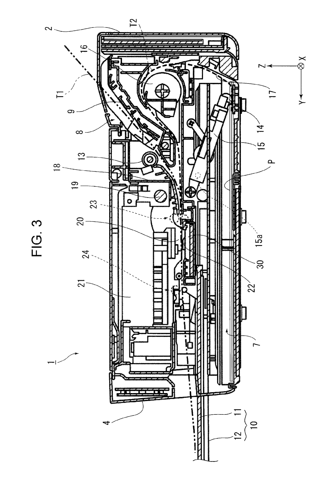
[0044]FIG. 1 is a perspective, external view of the printer 1, according to the present embodiment. FIG. 2 is a diagram illustrating a deployed state of a discharged paper tray in the printer 1, according to the present embodiment. FIG. 3 is a diagram illustrating a paper transport path of the printer 1, according to the present embodiment. FIG. 4 is a perspective view of the printer 1, illustrating a state in which the outer covering of an apparatus body of the printer 1 is removed. FIG. 5 is a side cross-sectional view of the vicinity of a recording head and a medium supporting portion of the printer 1. FIG. 6 is a perspective view of the medium supporting portion. FIG. 7 is a perspective ...

second embodiment

[0078]In this second embodiment, another example of the electric field forming section according to the invention will be described on the basis of FIG. 10. FIG. 10 is a diagram illustrating an electric field forming section according to this second embodiment. Note that, in the present embodiment and a subsequent embodiment, the same components as the components of the first embodiment will be denoted by the same reference signs as those of the components of the first embodiment, and thereby will be omitted from description.

[0079]Although, in the first embodiment, the first absorbing member 40 is provided on the upper side of the conductive member 31 (constituting the electric field forming section 30), in this second embodiment, as illustrated in FIG. 10, a conductive member 31, as a conductive member constituting an electric field forming section 50, is provided between the first absorbing member 40 and the recording head 20. That is, in this second embodiment, the electric field...

third embodiment

[0081]In this third embodiment, still another example of the electric field forming section according to the invention will be described on the basis of FIG. 11. FIG. 11 is a diagram illustrating an electric field forming section according to this third embodiment. The feature of an electric field forming section 51, as an electric field forming section according to this third embodiment, is that the electric field forming section 51 includes a second conductive member 36.

[0082]In the present embodiment, the second conductive member 36 is provided between the recording head 20 and the conductive member 31 in a height direction (in the Z-axis direction). Further, the second conductive member 36 is provided so as to extend across a reciprocation region of the carriage 21 in the apparatus width direction (in the X-axis direction).

[0083]In the case where an electric potential difference is formed between the conductive member 31 and the recording head 20 by applying a voltage to the con...


PUM


Abstract

A recording apparatus includes an electric field forming section including a conductive member and configured to form an electric field, and the conductive member includes at least one first portion and a second portion, each of the at least one first portion being disposed at a position being nearer the recording head than a position of the second portion and included in a corresponding one of at least one liquid discarding region each of which, in an execution of borderless recording, is used for the ejection of the liquid onto an outside of a corresponding one of at least one edge whose position corresponds to each of at least one predetermined size of a medium, the second portion being disposed in a recording region other than the at least one liquid discarding region.

Description

BACKGROUND1. Technical Field[0001]The present invention relates to recording apparatuses that perform recording by ejecting liquid onto a medium.2. Related Art[0002]In ink jet printers (hereinafter referred to as just printers) serving as the recording apparatuses and configured to perform recording by ejecting ink as the liquid from a recording head thereof, when the ink is ejected from the recording head, ink mist sometimes arises as the result of the change of the ejected ink into ink in a mist state (this ink mist being sometimes referred to as just “mist” hereinafter).[0003]Further, the mist floats and travels around to an upper portion of a carriage including the recording head. Further, the mist is sometimes adhered onto, for example, an ink cartridge mounted in the carriage. In the case where the mist is adhered on the ink cartridge, there is a risk that, when a user replaces the ink cartridge, the mist may soil the user's hand. Further, in the case where the mist is adhered...

Claims


Application Information

Patent Timeline
Patent Type & Authority Applications(United States)
IPC IPC(8): B41J2/165B41J2/14
CPCB41J2/14314B41J2/16517B41J11/0065B41J2/095B41J29/13B41J2/1714
Inventor ITO, TATSUYAYOSHINO, SATOSHISATO, MAKOTOTAMAI, KENSUKE
Owner SEIKO EPSON CORP
Why Eureka
Try Eureka