
Optical connector with optical fibers and method for manufacturing the same

Active Publication Date: 2019-01-10
FUJIKURA LTD
View PDF0 Cites 2 Cited by
  • Summary
  • Abstract
  • Description
  • Claims
  • Application Information

AI Technical Summary

Benefits of technology

The present invention provides an optical connector that can prevent bare optical fibers from bending and maintain good optical characteristics even in low-temperature environments or when optical fibers are pushed into the connector. The optical connector includes a multi-fiber optical connector and a plurality of buffered optical fibers with tubes, which are connected to the multi-fiber optical connector through a ferrule. Each of the buffered optical fibers has a bare fiber fixing portion closer to the ferrule than the tube fixing portion in the multi-fiber optical connector. The technical effects of this invention include improved optical performance and durability of optical connectors and a simplified manufacturing process.

Problems solved by technology

Therefore, the deterioration becomes more significant.

Method used


Image

  • Optical connector with optical fibers and method for manufacturing the same
  • Optical connector with optical fibers and method for manufacturing the same
  • Optical connector with optical fibers and method for manufacturing the same

Examples


Embodiment Construction

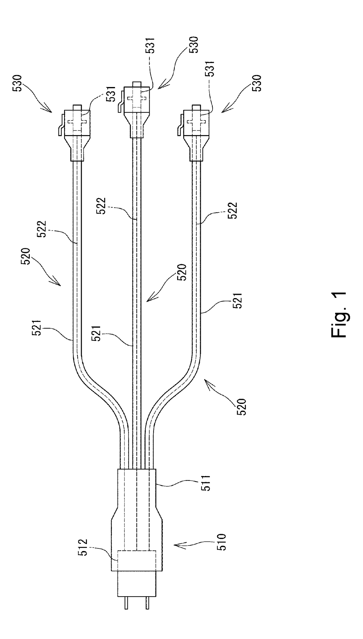
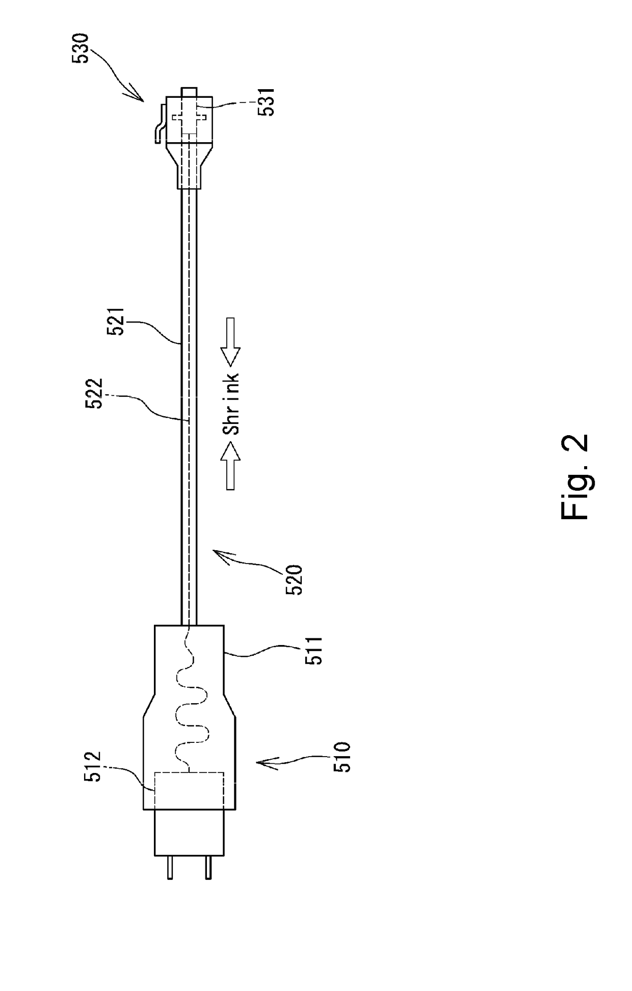
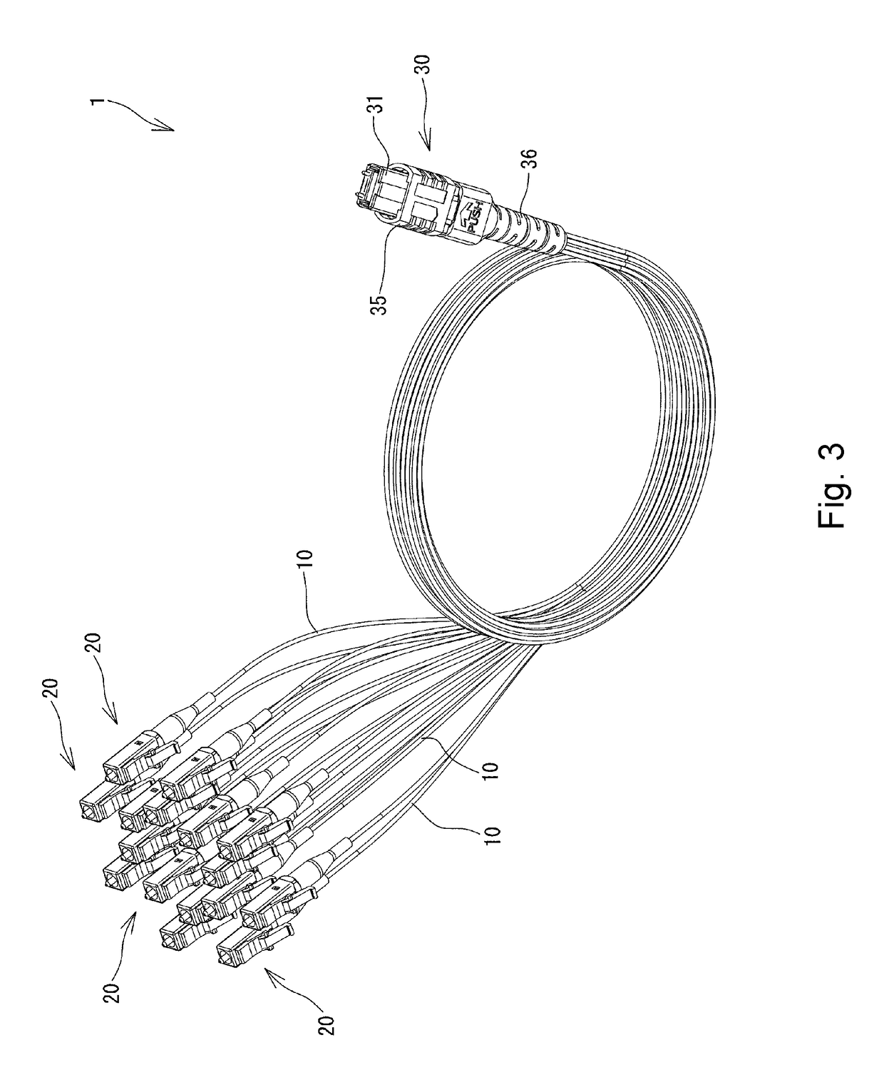
[0028]Embodiments of an optical connector with optical fibers according to the embodiments of the present invention will be described below with reference to FIGS. 3 to 8F. In FIGS. 3 to 8F, the same or corresponding components are denoted by the same or corresponding reference numerals and will not be described below repetitively. Furthermore, in FIGS. 3 to 8F, the scales or dimensions of components may be exaggerated, or some components may be omitted.

[0029]FIG. 3 is a perspective view showing an optical connector with optical fibers 1 according to one or more embodiments of the present invention. As shown in FIG. 3, the optical connector with optical fibers 1 includes a plurality of buffered optical fibers 10, single-fiber optical connectors 20 attached to ends of the respective buffered optical fibers 10, and a multi-fiber optical connector 30 attached to the other ends of the buffered optical fibers 10. The buffered optical fibers 10 are bundled at the root of the multi-fiber o...


PUM


Abstract

An optical connector attached to a plurality of buffered optical fibers each including: a bare optical fiber; and a tube in which the bare optical fiber is inserted in. A multi-fiber optical connector is connected to first ends of the buffered optical fibers, and a plurality of single-fiber optical connectors are respectively connected to second ends of the buffered optical fibers. The multi-fiber optical connector includes: a ferrule fixed to ends of the bare optical fibers; a connector housing that houses the ferrule therein; and a tube fixing portion that fixes the tubes to the connector housing. The buffered optical fiber has a bare fiber fixing portion in which the bare optical fiber and the tube are fixed at a location closer to the ferrule than the tube fixing portion within the multi-fiber optical connector.

Description

TECHNICAL FIELD[0001]The present invention relates to an optical connector with optical fibers and a method of manufacturing the same, and more particularly to an optical connector with optical fibers that includes a multi-fiber optical connector from which a plurality of buffered optical fibers are branched and a method of manufacturing the same.BACKGROUND[0002]There has heretofore been known an optical connector with optical fibers, what is called a fanout code, in which a plurality of buffered optical fibers are branched from a multi-fiber optical connector while single-fiber optical connectors are respectively connected to ends of the branched buffered optical fibers (see, e.g., Patent Literature 1). FIG. 1 is a diagram schematically showing a structure of a conventional optical connector with optical fibers. As shown in FIG. 1, the conventional optical connector with optical fibers includes a multi-fiber optical connector 510, a plurality of buffered optical fibers 520 branched...

Claims


Application Information

Patent Timeline
IPC IPC(8): G02B6/38G02B6/40
CPCG02B6/40G02B6/3861G02B6/3885G02B6/38875G02B6/36
Inventor OTOMITSU, TAKAHITO
Owner FUJIKURA LTD
Learn More