Eureka AIR delivers breakthrough ideas for toughest innovation challenges, trusted by R&D personnel around the world.

Lens apparatus, imaging apparatus, and intermediate accessory

a technology of lens and accessory device, applied in the field of lens apparatus, imaging apparatus, and intermediate accessory device, can solve the problem that the imaging apparatus erroneously distinguishes the type of accessory devi

Active Publication Date: 2018-12-06
CANON KK
View PDF0 Cites 22 Cited by
  • Summary
  • Abstract
  • Description
  • Claims
  • Application Information

AI Technical Summary

Benefits of technology

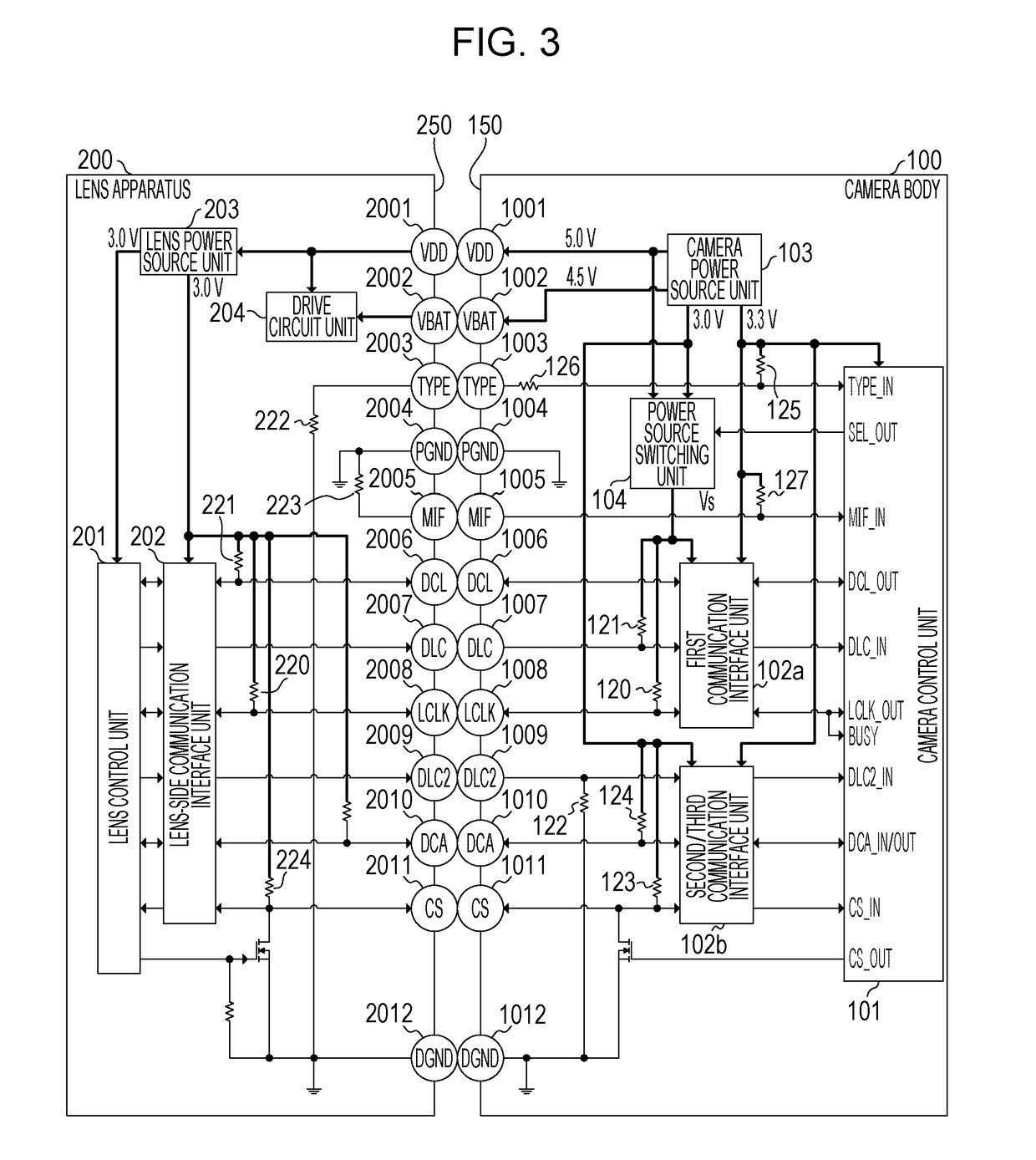
The present invention provides an imaging apparatus that can accurately identify the type of accessory device attached to it. This is achieved by a distinguishing unit that uses multiple electric contacts to distinguish the type of lens apparatus mounted on the imaging apparatus. The first electric contact is used to supply power to the lens apparatus, while the second and third electric contacts are used for communication. The third electric contact is specifically designed to distinguish between two different types of lens apparatus. This ensures that the imaging apparatus can communicate with the correct lens apparatus, even if multiple accessories are attached. The invention also includes an intermediate accessory device that can be detachably mounted on the imaging apparatus, allowing for the use of different lens apparatus without needing to replace the entire accessory device.

Problems solved by technology

If the electric contact for distinguishing an accessory device short-circuits with another electric contact, there are cases where the imaging apparatus erroneously distinguishes the type of accessory device that has been mounted.
However, US2013 / 0287388 does not take into consideration a case where the electric contact for distinguishing an accessory device short-circuits with another electric contact.

Method used


Image

  • Lens apparatus, imaging apparatus, and intermediate accessory
  • Lens apparatus, imaging apparatus, and intermediate accessory
  • Lens apparatus, imaging apparatus, and intermediate accessory

Examples


Embodiment Construction

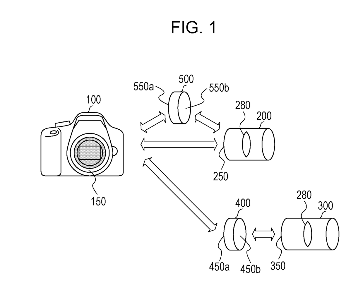
[0027]Various types of terminology used in the specification of the present application will be described prior to the description relating to embodiments of the present invention. The term “accessory apparatus (device)” refers to a device that is mountable to an imaging apparatus (image pick-up apparatus). The imaging apparatus and accessory device are mounted by coupling of mount units that each has. Accessory devices include lens apparatuses (lens devices) having an image-taking optical system. Accessory devices also include an intermediate accessory mounted between a lens apparatus and the imaging apparatus body.

[0028]The term “mount unit (portion)” is a coupling unit, provided to each of the imaging apparatus and accessory device. The mount unit of the imaging apparatus and the mount unit of the accessory device each are provided with electric contacts and the electric contacts (electric terminals) provided to the respective mount units come into contact when the accessory devi...


PUM


Abstract

In a camera body, a VBAT terminal and PGND terminal are both disposed adjacent to a TYPE terminal. In a case where the voltage of the TYPE terminal is a voltage of a first voltage range that does not include the VBAT voltage and does not include the voltage of the PGND terminal, a camera control unit distinguishes the mounted lens apparatus to be a first lens apparatus. In a case where the voltage of the TYPE terminal is a voltage of a second voltage range that is a voltage range different from the first voltage range, does not include the VBAT voltage and does not include the voltage of the PGND terminal, the camera control unit distinguishes the mounted lens apparatus to be a second lens apparatus.

Description

BACKGROUND OF THE INVENTIONField of the Invention[0001]The present invention relates to a lens apparatus, an imaging apparatus, and an intermediate accessory device, that are capable of communicating with each other.Description of the Related Art[0002]Accessory devices such as interchangeable lenses that are detachably mountable to an imaging apparatus operate by receiving a supply of power from the imaging apparatus, communicating with the imaging apparatus, and so forth. Accordingly, multiple electric contacts are provided both on a mount unit on the imaging apparatus and a mount unit on the accessory device. When an accessory device is mounted to the imaging apparatus, the electric contacts at the imaging apparatus side and the electric contacts at the accessory device side come into contact, and the imaging apparatus and the accessory device are electrically connected. In a case where multiple types of accessory devices having different operation voltages are mountable to the im...

Claims


Application Information

Patent Timeline
IPC IPC(8): H04N5/232H04N5/225G03B17/14
CPCH04N5/23209H04N5/2254G03B17/14G03B17/565H04N23/55G03B7/20G03B17/56H04N23/663
Inventor TSUKAMOTO, SUGURUWATAZAWA, YASUYUKIFUJIHASHI, NAOTO
Owner CANON KK
Why Eureka
Eureka Blog
Learn More