
Stirrer set and stirring device

a stirring device and stirrer technology, which is applied in the direction of mechanical equipment, transportation and packaging, and magnetic stirrers, can solve the problems of unavoidable cross-contamination, contamination of reaction solutions, and less suitable magnetic stirrers than conventional mechanical stirrers, so as to reduce friction loss, reduce manufacturing, repair, maintenance and other processes. the effect of cost reduction

Inactive Publication Date: 2018-12-06
TAIWAN ADVANCED NANOTECH
View PDF2 Cites 6 Cited by
  • Summary
  • Abstract
  • Description
  • Claims
  • Application Information

AI Technical Summary

Benefits of technology

The present invention provides a stirrer set and a stirring device that have simple structures and can help reduce manufacturing, repair, maintenance, and other costs. The design also overcomes limitations caused by gear mechanical structure to provide higher design flexibility and reduce element replacement rates. The stirring device may further comprise a bar magnet for additional magnetic effects. The present invention allows for more stirrer sets to be arranged in different patterns and increase or reduce operating volume according to user's needs.

Problems solved by technology

However, problems with a vibrating stirrer still exist: air may enter into samples during vibrations and result in contaminations, or cross-sectional areas of its elements are not compatible with other devices.
Nevertheless, due to dimension limits of a stir bar (which comes in various models and sizes), a magnetic stirrer stirs well only for liquids used in relatively small experiments (i.e. volume of a solution less than 4 liters).
For stirring high-volume solutions and viscous liquids, by contrast, a magnetic stirrer is far less suitable than a conventional mechanical stirrer.
Once a magnetic stir bar of the stirrer is contaminated, contamination to the reaction solutions is very likely to ensue.
But if too many samples are put and mixed within such a limited space, cross-contamination is still unavoidable.
However, due to the limitations of gears resulting from the mechanical structures, a new type of stirrer is still needed.

Method used

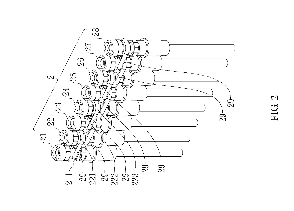
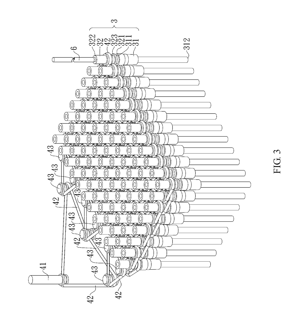

Image

  • Stirrer set and stirring device
  • Stirrer set and stirring device
  • Stirrer set and stirring device

Examples


Embodiment Construction

[0036]Details of one or more embodiments of the present invention will be provided in the accompanying drawings and the description below. The features, purposes and strengths of the present invention may be easily understood based on the description, accompanying drawings as well as claims. In order to illustrate these features and strengths in a clearer and more comprehensible manner, several exemplary embodiments are detailed as below with reference to the accompanying drawings.

[0037]While the strengths and features of the present invention may be better understood through detailed descriptions of the exemplary embodiments and the accompanying drawings, the invention may also be achieved in various forms and should not be construed as limited to the embodiments mentioned herein. However, to a person having ordinary skill in the art, the scope of the invention will become more thorough and comprehensible with these exemplary embodiments, yet the invention is defined by the appende...


PUM


Abstract

The present invention provides a stirrer set, comprising: a fitting tube having an opening portion and a hollow rotating shaft fitted into the opening portion, the hollow rotating shaft having an external wall which is annularly recessed to form at least one annular groove. The present invention also provides a stirring device, wherein a drive element comprising a power transmission element, such as a belt, may be rotatably driven to cause, via the power transmission element, the stirrer set to rotate for performing a stirring function. As such, the stirring device provides higher design flexibility when dealing with high-flux samples, and the element replacement rates can be significantly reduced. Thus, the costs related to manufacturing, repair, maintenance and other processes can be reduced in an effective manner.

Description

BACKGROUNDTechnical Field[0001]The present invention relates to a stirrer set and a stirring device; more particularly, the present invention provides a stirrer set having annular grooves, and a stirring device wherein the stirrer set is driven by a power transmission element (such as a belt) for performing a stirring function.Description of Related Art[0002]There are many types of stirrers that can be found on the market, such as vibrating stirrers or magnetic stirrers. Stirrers can be used to stir solutions and reagents in order to accelerate the dissolution of a solute or prevent coagulation.[0003]A vibrating stirrer is a device manufactured by including a piezoelectric ceramic transducer that is able to convert a voltage to mechanical vibrations. This device is designed for carrying out steps of a biological or chemical analysis (including steps such as solidification, wash or interaction), and generally comprises a vibrating unit for which vibration frequencies can be controlle...

Claims


Application Information

Patent Timeline
Patent Type & Authority Applications(United States)
IPC IPC(8): B01F15/00B01F13/10B01F7/16B01F13/08
CPCB01F15/00454B01F13/1022B01F7/161B01F13/08F16H7/06F16H7/02F16H35/18B01F27/806B01F27/94B01F33/053B01F33/45B01F33/813B01F35/3231
Inventor CHIEN, CHIEN-HSINGHUANG, CHING-JULU, KUAN-MINGSUN, SU-CHIN
Owner TAIWAN ADVANCED NANOTECH
Learn More