
Motion mirroring system that incorporates virtual environment constraints

Active Publication Date: 2018-11-29
NEWLIGHT CAPITAL LLC
View PDF2 Cites 13 Cited by
  • Summary
  • Abstract
  • Description
  • Claims
  • Application Information

AI Technical Summary

Benefits of technology

This patent describes a system that can move an object in a virtual game or simulation based on events that occur. The object can be relocated automatically or in response to user input. The system can also adjust the object's orientation to match its current position. This allows for a more realistic and smooth movement of objects in virtual spaces.

Problems solved by technology

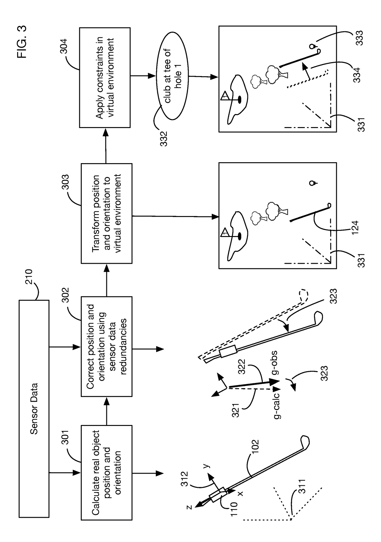
Because these calculations may result in errors, including potentially accumulating errors over time, the computer may apply one or more corrections to the position and orientation, for example using redundancies in the sensor data.

Method used


Image

  • Motion mirroring system that incorporates virtual environment constraints
  • Motion mirroring system that incorporates virtual environment constraints
  • Motion mirroring system that incorporates virtual environment constraints

Examples


Embodiment Construction

[0026]A motion mirroring system that incorporates virtual environment constraints will now be described. In the following exemplary description numerous specific details are set forth in order to provide a more thorough understanding of the ideas described throughout this specification. It will be apparent, however, to an artisan of ordinary skill that embodiments of ideas described herein may be practiced without incorporating all aspects of the specific details described herein. In other instances, specific aspects well known to those of ordinary skill in the art have not been described in detail so as not to obscure the disclosure. Readers should note that although examples of the innovative concepts are set forth throughout this disclosure, the claims, and the full scope of any equivalents, are what define the invention.

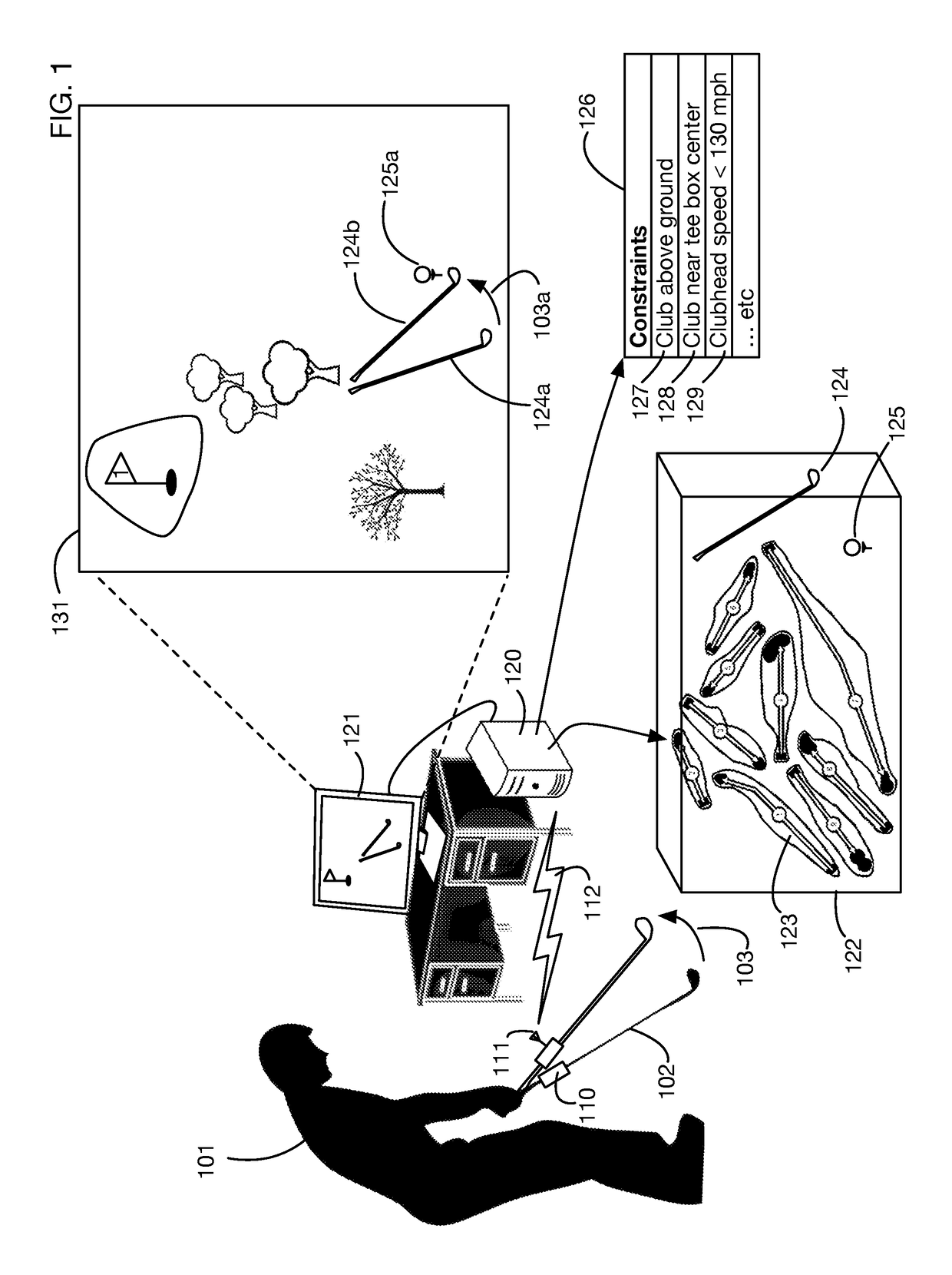
[0027]FIG. 1 shows an illustrative embodiment of the system that mirrors the motion of a golf club by displaying a virtual golf club whose motion is synchronized...


PUM


Abstract

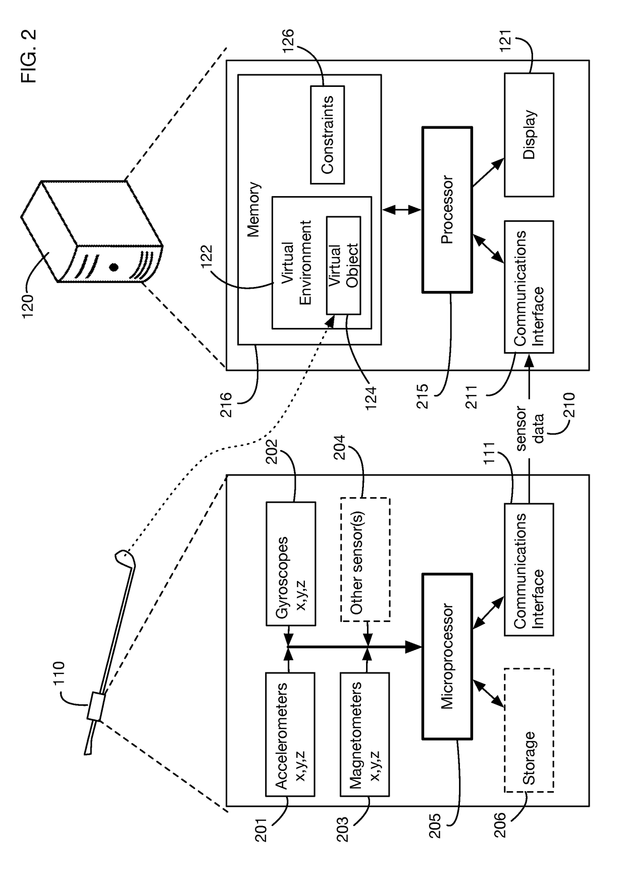
A system that mirrors motion of a physical object by displaying a virtual object moving in a virtual environment. The mirroring display may be used for example for feedback, coaching, or for playing virtual games. Motion of the physical object is measured by motion sensors that may for example include an accelerometer, a gyroscope, and a magnetometer. Sensor data is transmitted to a computer that calculates the position and orientation of the physical object and generates a corresponding position and orientation of the virtual object. The computer may correct or adjust the calculations using sensor data redundancies. The virtual environment may include constraints on the position, orientation, or motion of the virtual object. These constraints may be used to compensate for accumulating errors in position and orientation. The system may for example use proportional error feedback to adjust position and orientation based on sensor redundancies and virtual environment constraints.

Description

BACKGROUND OF THE INVENTIONField of the Invention[0001]One or more embodiments setting forth the ideas described throughout this disclosure pertain to the field of motion capture sensors and displaying motion data in a virtual reality environment. More particularly, but not by way of limitation, one or more aspects of the invention enable a system that mirrors the motion of a real object with motion of a virtual object in a virtual environment, and that applies constraints defined in the virtual environment to the motion of the virtual object.Description of the Related Art[0002]Motion capture sensors and systems for analyzing motion data are known in the art, but these systems typically provide delayed analysis or playback after events occur. For example, there are systems that analyze the swing of a golf club using motion sensors attached to the club; these systems wait until a swing signature is detected, and then analyze the sensor data to reconstruct and diagnose the swing. Exis...

Claims


Application Information

Patent Timeline
Patent Type & Authority Applications(United States)
IPC IPC(8): A63F13/211G06T19/00A63F13/25A63F13/812A63F13/525A63F13/833A63F13/235
CPCA63F13/211G06T19/006A63F13/25A63F13/812A63F2300/8082A63F13/833A63F13/235G06T15/20A63F2300/105A63F13/525A63F13/42
Inventor HAAS, JUERGENBOSE, BHASKARBENTLEY, MICHAELKAPS, RYAN
Owner NEWLIGHT CAPITAL LLC
Learn More