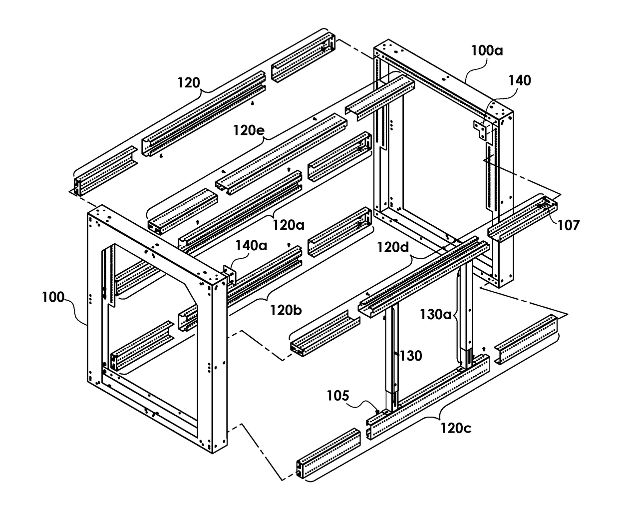
Modular flat-pack apparatus for customizable cabinetry framing

Active Publication Date: 2018-11-08
NEW ENGLAND WELDING INC
View PDF10 Cites 4 Cited by
  • Summary
  • Abstract
  • Description
  • Claims
  • Application Information

AI Technical Summary

Benefits of technology

[0006]The present invention meets all these needs, by disclosing apparatus and methods for modular cabinetry framing components. The goal of the present invention is to provide a solution for modular cabinetry framing, which framing may be customized on-site for a wide range of desired uses. The present invention provides for apparatus that may be made in a production facility, packed in relatively flat boxes for warehousing, shipping, or distribution, and assembled on-site easily, by builders, contractors, or end users. The apparatus comprises modules which may be assembled on-site from a small set of types of components, which components may be used in various ways and combinations to make different modules. The components so produced, and the modules assembled from those components, are strong due to the materials used and methods of assembly, and relatively affordable due to the ability to mass-produce standard components which can be assembled into custom configurations. The customized modular cabinetry modules so produced are also relatively affordable due to the ability to ship them and stock them in relatively compact containers. Thus, the present invention also provides for increased choice of types of modules relative to pre-fabricated whole modules, because the components can be adjusted and sized to fit particular desired installations. Additionally, the prese

Problems solved by technology

Cabinetry framing is typically expensive to build and install due to the cost of labor, because nearly every installation requires some customization in fitting materials or parts to the desired job site to build the desired cabinetry framing.
There is a relation between cost of labor and cost of materials in building custom cabinetry framing: low materials costs, such as for wood framing, typically require more time to plan, cut, and assemble, leading to increased labor costs.
Additionally, such solutions can be plagued by inconsistent quality of the construction, leading to weak structures, parts that don't fit, or leaks.
To make custom cabinetry framing that is weather-proof such that it can be used outdoors, some builders have used materials such as drywall studs, which may be easily cut and fastened together—but such a product is very likely not structurally sound enough to support heavy materials, such as concrete backing board, stonework, stone countertops, sinks, and grills.
Conversely, labor costs can be lowered by building custom cabinetry in a factory, and build quality can be high, but the costs for materials, storage, and shipping will all very likely increase dramatically.
Custom cabinetry, and whether pre-fabricated or built-to-order, generally contains many unique parts, driving up both supply chain complexity and cost, cost of assembly, and cost of packing.
Furthermore, pre-fabricated custom cabinetry will present far fewer choices for the builder and end user in what they can install and how they can use the space where they want to install the custom cabinetry, if the factory produces only a few modules.
Alternatively, the factory costs for the pre-fabricated modules will be high, if the factory maintains assembly lines and plans for a wide range of pre-fabricated modules.
Whether a factory's pre-fabricated framing modules present a problem of few choices and/or a problem of especially high costs for offering many pre-fabricated modules, the costs for materials, storage, and shipping will remain a problem for builders and end users.
Additionally, pre-fabricated modules assembled in a factory pos

Method used


Image

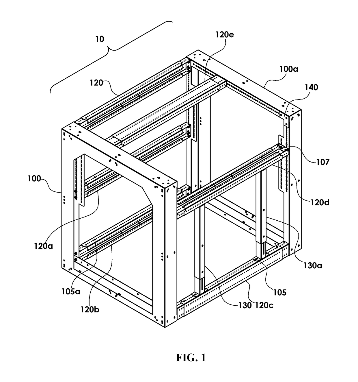
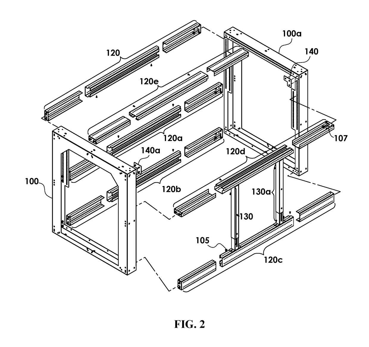
  • Modular flat-pack apparatus for customizable cabinetry framing
  • Modular flat-pack apparatus for customizable cabinetry framing
  • Modular flat-pack apparatus for customizable cabinetry framing

Examples


Example

DETAILED DESCRIPTION OF THE DRAWINGS

[0066]The presently disclosed invention is described with specificity to meet statutory requirements. But, the description itself is not intended to limit the scope of this patent. Rather, the claimed invention might also be embodied in other ways, to include different steps or elements similar to the ones described in this document, in conjunction with other present or future technologies. Moreover, although the term “step” or similar terms may be used herein to connote different aspects of methods employed, the term should not be interpreted as implying any particular order among or between various steps herein disclosed unless and except when the order of individual steps is explicitly described.

[0067]In the following description, numerous specific details are set forth to provide a thorough understanding of the invention. But, the present invention may be practiced without these specific details. Structures and techniques that would be known t...


PUM

PropertyMeasurementUnit
Lengthaaaaaaaaaa
Shapeaaaaaaaaaa
Widthaaaaaaaaaa

Abstract

Systems and methods are provided for customizable cabinetry framing. The systems presented describe components which can be assembled into customizable framing modules for cabinetry in outdoor kitchens, farming sheds, restaurants, warehouses, or more. The methods presented describe making each component by cutting sheet metal or other sheet material, and then by folding the cut sheet metal, and using some fasteners. Standardized components may be assembled on-site into customized modules. These materials and assembly eliminate the need for costly and time-consuming welding at point of manufacture or assembly, while providing advantages in strength of the assembled framing modules. Various components may be packed for shipping in relatively flat units. The present invention solves problems with the currently available means of manufacturing and assembling outdoor kitchens and other custom framing built on-site. Lower costs of materials, manufacture, shipping, and labor for assembly result in more cost-effective and/or stronger framing.

Description

FIELD OF THE INVENTION[0001]The presently disclosed subject matter relates to providing modular and customizable framing for outdoor kitchens and other uses of customizable cabinetry framing.BACKGROUND OF THE INVENTION[0002]Builders and craftsmen have been making custom cabinetry framing for centuries, and various solutions have been proposed to lower the cost of materials and labor. Cabinetry framing is typically expensive to build and install due to the cost of labor, because nearly every installation requires some customization in fitting materials or parts to the desired job site to build the desired cabinetry framing. There is a relation between cost of labor and cost of materials in building custom cabinetry framing: low materials costs, such as for wood framing, typically require more time to plan, cut, and assemble, leading to increased labor costs. Additionally, such solutions can be plagued by inconsistent quality of the construction, leading to weak structures, parts that...

Claims


Application Information

Patent Timeline
IPC IPC(8): A47B47/02A47B45/00A47B47/00A47B77/08
CPCA47B47/027A47B45/00A47B47/0091A47B77/08A47B47/0008
Inventor BOVA, SALVATOREMCINTIRE, KENNETHCHUCKRAN, ERIC
Owner NEW ENGLAND WELDING INC
Why Eureka
Try Eureka