Base station apparatus and terminal device

a terminal device and base station technology, applied in the direction of orthogonal multiplex, multiplex communication, transmission path division, etc., can solve the problem of limit of an available frequency band, and achieve the effect of efficient sharing of information

Active Publication Date: 2018-10-25
SHARP KK
View PDF4 Cites 3 Cited by
  • Summary
  • Abstract
  • Description
  • Claims
  • Application Information

AI Technical Summary

Benefits of technology

[0020]According to the present invention, it is possible to efficiently share information indicating whether a base station apparatus and a terminal device is able to use an unlicensed band or is not able to use due to the reason why another system occupies the unlicensed band.

Problems solved by technology

The LTE system or the LTE-A system needs to cope with a rapid increase in data traffic, and the introduction of a technology for improving a peak data rate or spectral efficiency and the reservation of frequency resources are important issues.
In the LTE system or the LTE-A system so far, the use of a frequency band referred to as a so-called licensed band permitted for use from a country or a locality in which a radio communication operator provides services is assumed, and there are limitations of an available frequency band.

Method used


Image

  • Base station apparatus and terminal device
  • Base station apparatus and terminal device
  • Base station apparatus and terminal device

Examples


first embodiment

1. First Embodiment

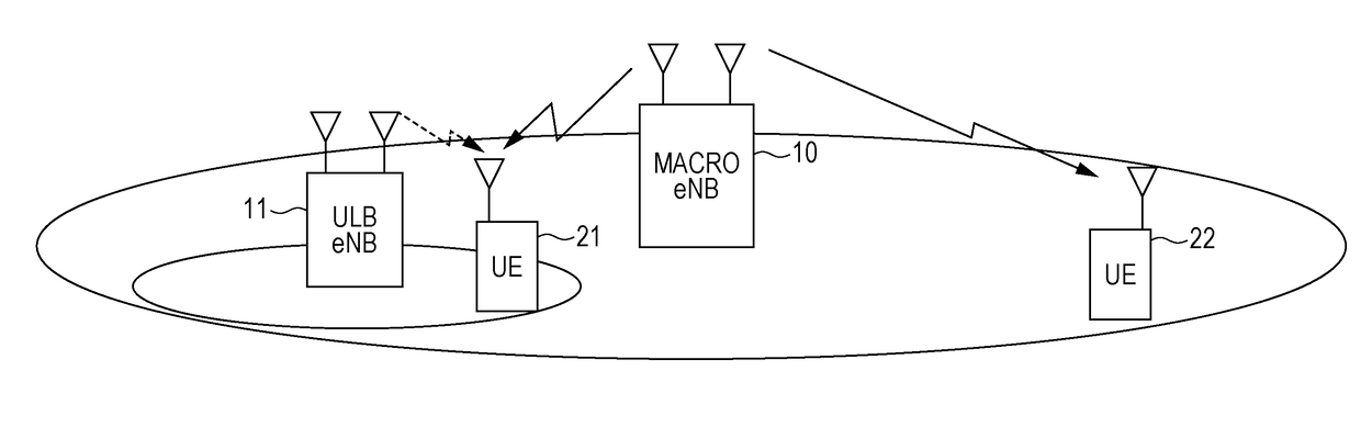
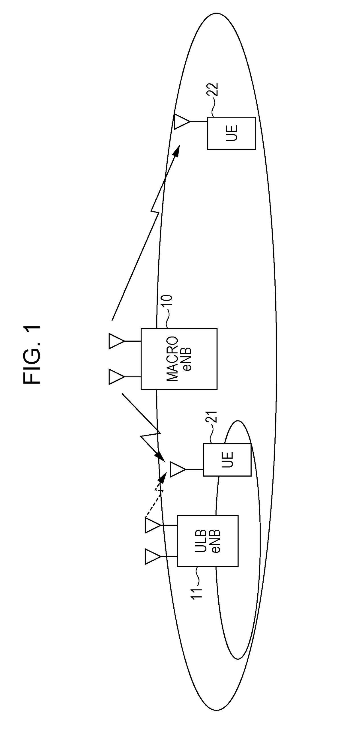
[0036]Hereinafter, an embodiment will be described with reference to the drawings. FIG. 1 illustrates an example of a structure of a system according to the present invention. The system includes a macro base station apparatus 10, a ULB base station apparatus 11, and terminal devices 21 and 22. The number of terminal devices (terminals, mobile terminals, mobile stations, or user equipment (UE)) is not limited to 2, and the number of antennas of each device may be 1, or may be plural in number. It is assumed that the macro base station apparatus 10 performs communication using a so-called licensed band of which permission for use is gained by a country or a locality where a radio communication operator provides services and the ULB base station apparatus 11 performs communication using a so-called unlicensed band which does not require the permission for use by the country or locality, but the present invention is not limited to this example. For example, the macro...

modification example 1 of first embodiment

[0059]In the present modification example, structure examples of the ULB base station apparatus and the terminal device are the same as those of the first embodiment, and are respectively illustrated in FIGS. 4 and 6. A structure example of the DL signal generation unit 101 of the ULB base station apparatus is also the same as that of the first embodiment, and is illustrated in FIG. 5. Thus, only different processes will be described in the present modification example, and the description of the same processes will be omitted.

[0060]In the present modification example, the CS determination unit 106 and the synchronization signal multiplexing units 1013-1 and 1013-2 of the ULB base station apparatus are different from those of the first embodiment. The CS determination unit 106 determines whether or not another system uses the ULB-CC in the subframe of the carrier sense. Here, although it has been described in the first embodiment that the carrier sense is performed during all the pe...

modification example 2 of first embodiment

[0068]In the present modification example, structure examples of the ULB base station apparatus and the terminal device are the same as those of the first embodiment, and are respectively illustrated in FIGS. 4 and 6. A structure example of the DL signal generation unit 101 of the ULB base station apparatus is also the same as that of the first embodiment, and is illustrated in FIG. 5. Thus, only different processes will be described in the present modification example, and the description of the same processes will be omitted.

[0069]In the present modification example, the PSS / SSS is transmitted by the same method as that of Modification Example 1 of the first embodiment, and is allocated to the last OFDM symbol of the subframe of the carrier sense. Here, the UL signal generation unit 211 of the terminal device is different from that of Modification Example 1 of the embodiment. The UL signal generation unit 211 generates a transmit signal of the uplink based on the information of th...


PUM


Abstract

In an LTE-A system, there is a problem that it is difficult to perform stable communication in a case where there is a time when another system occupies an unlicensed band being used. There is provided a base station apparatus that communicates with a terminal device in a second frequency band different from a first frequency band capable of being used as a dedicated frequency band. The base station apparatus includes: a wireless transmission unit that transmits data or control information to the terminal device; and a wireless reception unit that receives data or control information transmitted from the terminal device. The wireless transmission unit transmits data to the terminal device, and the wireless reception unit performs a process of receiving ACK / NACK transmitted from the terminal device in a subframe of an initial uplink after communication of another system is ended in a case where the other system performs the communication in the second frequency band at a reception timing of the ACK / NACK of the data transmission.

Description

TECHNICAL FIELD[0001]The present invention relates to a base station apparatus and a terminal device.BACKGROUND ART[0002]The standardization of a Long Term Evolution (LTE) system which is a wireless communication system (Rel. 8 and Rel. 9) of 3.9G mobile phones has been completed, and the standardization of LTE-Advanced (LTE-A) (also referred to as IMT-A) system (from Rel. 10 onwards) which is an enhancement of the LTE system as one of 4G wireless communication systems has been currently performed.[0003]The LTE system or the LTE-A system needs to cope with a rapid increase in data traffic, and the introduction of a technology for improving a peak data rate or spectral efficiency and the reservation of frequency resources are important issues. In the LTE system or the LTE-A system so far, the use of a frequency band referred to as a so-called licensed band permitted for use from a country or a locality in which a radio communication operator provides services is assumed, and there ar...

Claims


Application Information

Patent Timeline
Patent Type & Authority Applications(United States)
IPC IPC(8): H04W72/04H04W16/14H04L1/18H04J11/00H04L5/00H04W72/12H04W74/08
CPCH04W72/1215H04L5/001H04L1/1861H04L1/1854H04L5/0055H04W72/0446H04W74/0808H04W16/14H04W72/0453H04W72/0406H04J11/00H04J11/0073H04J11/0076H04W72/20
Inventor GOTO, JUNGONAKAMURA, OSAMUTOMEBA, HIROMICHIWAKAHARA, SHIROHAMAGUCHI, YASUHIRO
Owner SHARP KK
Why Eureka
Try Eureka