Centrifugal compressor

a centrifugal compressor and compressor technology, applied in the direction of non-positive displacement fluid engines, radial flow pumps, non-positive displacement pumps, etc., can solve the problem of lower efficiency of speed increasers, and achieve the effect of reducing agitation resistan

Active Publication Date: 2018-10-04
TOYOTA IND CORP
View PDF7 Cites 5 Cited by
  • Summary
  • Abstract
  • Description
  • Claims
  • Application Information

AI Technical Summary

Benefits of technology

[0005]It is an object of the present invention to provide a centrifugal compressor that reduces the agitation resistance.

Problems solved by technology

This will increase the agitation resistance when the ring member rotates and lower the efficiency of the speed increaser.

Method used


Image

  • Centrifugal compressor
  • Centrifugal compressor
  • Centrifugal compressor

Examples


Embodiment Construction

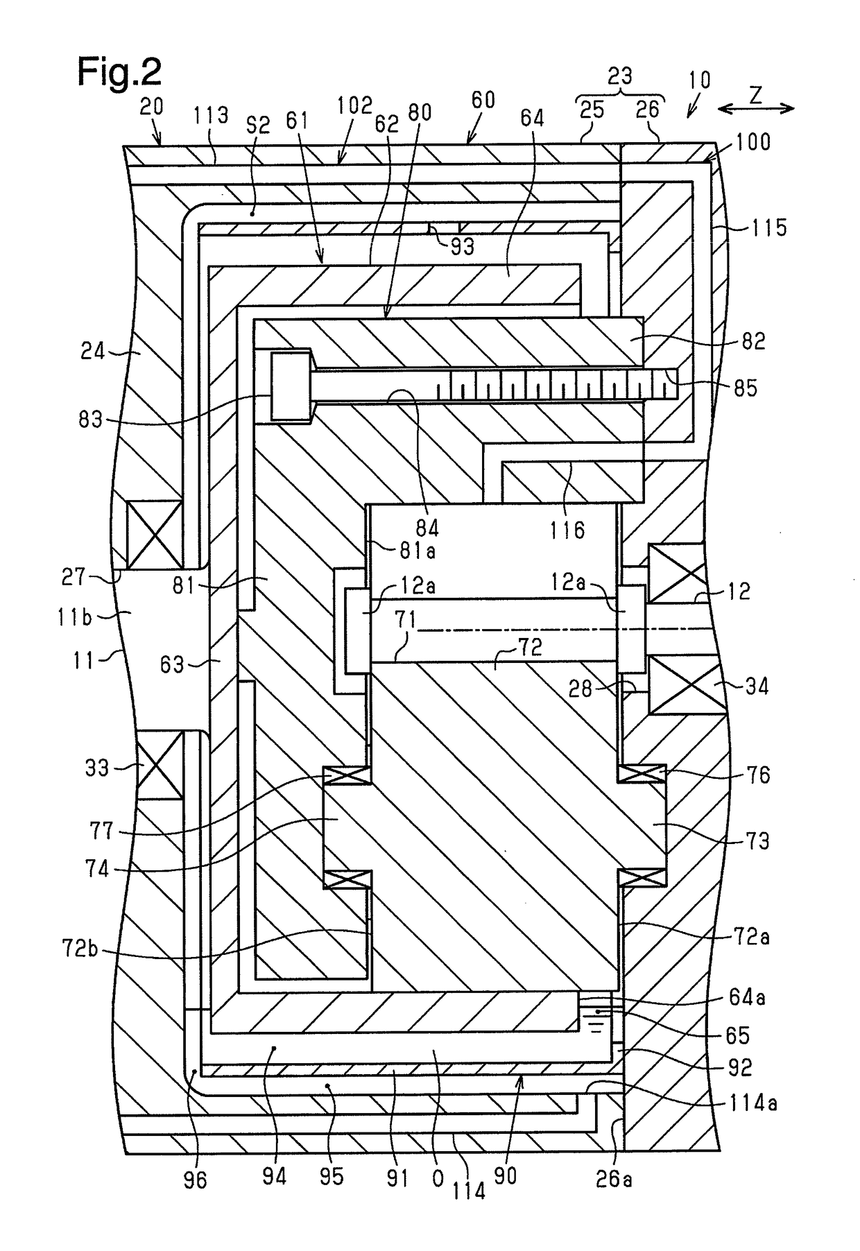
[0013]One embodiment of a centrifugal compressor will now be described. The centrifugal compressor of the present embodiment includes a speed increaser and is installed in a fuel cell vehicle (FCV) that is powered by a fuel cell. The centrifugal compressor supplies the fuel cell with air.

[0014]As shown in FIG. 1, a centrifugal compressor 10 includes a low-speed shaft 11, a high-speed shaft 12, an electric motor 13 that rotates the low-speed shaft 11, a speed increaser 60, and an impeller 52. The speed increaser 60 increases the rotation speed of the low-speed shaft 11 and transmits the rotation to the high-speed shaft 12. The impeller 52 is rotated by the high-speed shaft 12 to compress fluid (air in the present embodiment). The two shafts 11 and 12 are formed from, for example, a metal, specifically, iron or an iron alloy.

[0015]The centrifugal compressor 10 includes a housing 20 that forms the outer shell of the centrifugal compressor 10. The housing 20 accommodates the two shafts ...


PUM


Abstract

A centrifugal compressor includes an electric motor coupled to a low-speed shaft, an impeller, and a speed increaser. The speed increaser includes a ring member, a high-speed shaft, rollers, a speed increaser housing member, a discharge passage, and a partition. The ring member includes a circumferential wall and is rotated when the low-speed shaft rotates. The high-speed shaft is coupled to the impeller. The rollers are located between the circumferential wall and the high-speed shaft. The speed increaser housing member stores oil. The discharge passage discharges oil out of the ring member. The partition is located between the speed increaser housing member and the circumferential wall in the radial direction. Power is transmitted from the low-speed shaft to the high-speed shaft by the ring member and the rollers.

Description

BACKGROUND ART[0001]The present invention relates to a centrifugal compressor.[0002]Japanese Laid-Open Patent Publication No. 2016-186238 describes an example of a compressor including a speed increaser. One example of a speed increaser includes a ring member, a high-speed shaft, rollers, and a speed increaser chamber. The rotation of a low-speed shaft rotates the ring member. The high-speed shaft is located at the inner side of the ring member. The rollers are located between the ring member and the high-speed shaft in contact with both of the ring member and the high-speed shaft. The speed increaser chamber accommodates the ring member, the high-speed shaft, and the rollers.[0003]In the speed increaser, the location where the rollers contact the ring member and the location where the rollers contact the high-speed shaft need to be oiled to reduce wear and avoid seizure.[0004]The compressor of Japanese Laid-Open Patent Publication No. 2016-186238 includes a reservoir chamber that i...

Claims


Application Information

Patent Timeline
Patent Type & Authority Applications(United States)
IPC IPC(8): F04D25/02F04D17/10F04D29/059F04D29/063
CPCF04D25/02F04D17/10F04D29/059F04D29/063F04D25/06F04D25/028F04D25/0606
Inventor FUKUYAMA, RYOSUKEITO, SHOGOTAKEUCHI, KAHO
Owner TOYOTA IND CORP
Why Eureka
Try Eureka