Mri-safe implantable lead assembly

a lead assembly and implantable technology, applied in the field of mri-safe implantable lead assemblies, can solve the problems of inducing electric current in parts of the system, dangerous current induced in the implantable lead assemblies by an electro-magnetic field of an mri procedure, and causing damage or discomfort, so as to mitigate the effects of current, dissipate induced current, and reduce curren

Active Publication Date: 2018-09-20
LIVANOVA USA INC
View PDF2 Cites 0 Cited by
  • Summary
  • Abstract
  • Description
  • Claims
  • Application Information

AI Technical Summary

Benefits of technology

This patent is about a medical device system, lead, or component that is designed to prevent or minimize the formation of electric current, mitigate the effects of an electric current, and prevent or limit the impact on patient tissue caused by an electro-magnetic field. The device is specifically designed to prevent overheating and injury during magnetic resonance imaging procedures (MRI) or other medical procedures that may use an electro-magnetic field. The device has an impedance threshold that allows it to safely dissipate induced current without causing significant localized heating. This means that patients can undergo MRI or other procedures without needing to remove the device. The technical effects are that the device prevents injury and ensures patient safety during medical procedures.

Problems solved by technology

However, an electro-magnetic field used during the MM procedure can induce electric currents in portions of the system, such as the implantable lead assembly.
A current induced in an implantable lead assembly by an electro-magnetic field of an MRI procedure can be dangerous for the patient.
For example, if the current is applied to the tissue of the patient, the current can cause damage or discomfort.

Method used


Image

  • Mri-safe implantable lead assembly
  • Mri-safe implantable lead assembly
  • Mri-safe implantable lead assembly

Examples


Embodiment Construction

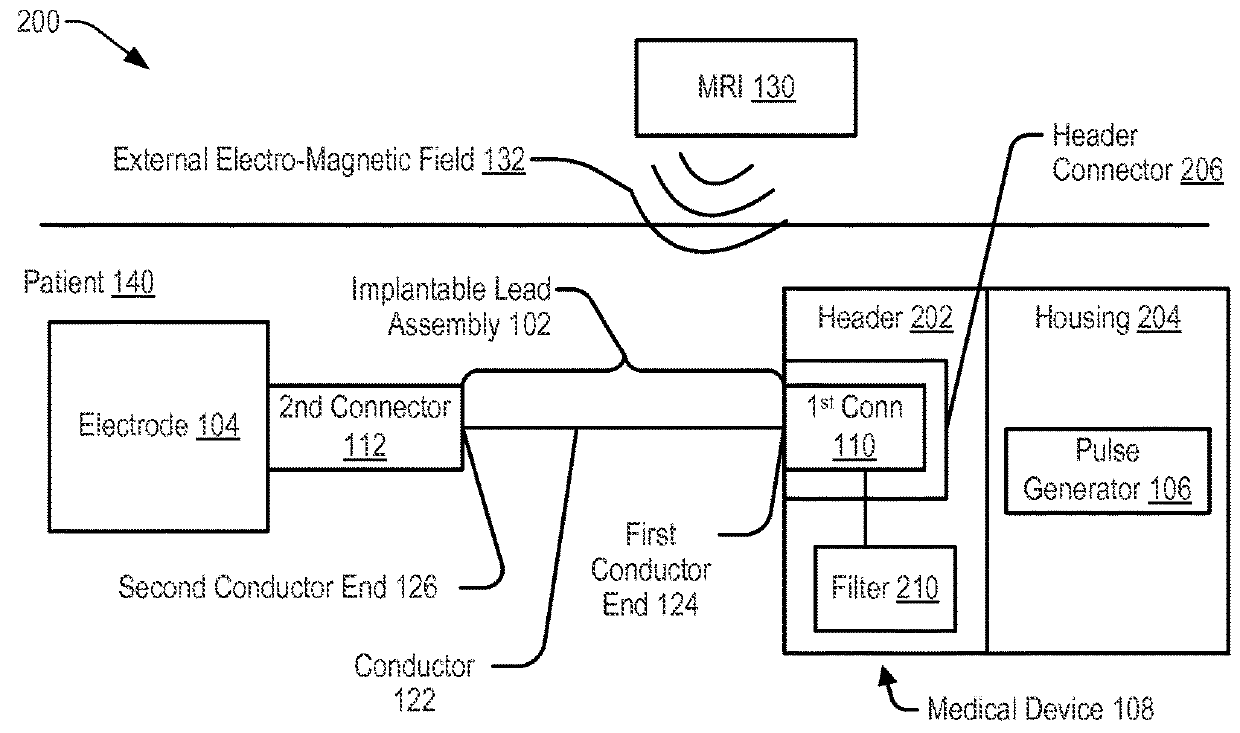
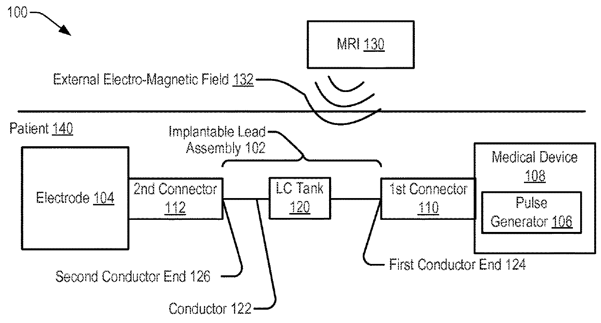
[0037]Referring to FIG. 1, a system 100 including an implantable lead assembly 102 is shown. The implantable lead assembly 102 may be coupled, via a first connector 110, to a medical device 108 and may be coupled, via a second connector 112, to an electrode 104. The implantable lead assembly 102 may include a conductor 122 extending from a first conductor end 124 to a second conductor end 126. The first conductor end 124 may be coupled, via the first connector 110, to the pulse generator 106. The second conductor end 126 may be coupled, via the second connector 112, to the electrode 104.

[0038]In a particular embodiment, the system 100, or a portion thereof, may be implanted within tissue of a patient 140 to provide therapy or to sense information from the tissue of the patient 140. For example, the electrode 104 may be configured to sense information related to tissue of a patient 140 (e.g., electrical signals generated by a nerve of the patient 140) and to provide the information t...


PUM


Abstract

A medical device includes a pulse generator and a filter. The pulse generator is configured to generate a stimulation signal and to provide the stimulation signal to tissue of a patient via an implantable lead assembly. The filter is configured to couple to the implantable lead assembly. A combined impedance of the implantable lead assembly and the filter with respect to a current induced by an external electro-magnetic field satisfies an impedance threshold when the external electro-magnetic field has a first frequency and when the external electro-magnetic field has a second frequency. The combined impedance has a peak impedance value when the external electro-magnetic field has a third frequency that is between the first frequency and the second frequency.

Description

CROSS-REFERENCE TO RELATED APPLICATIONS[0001]This application is a divisional application of U.S. application Ser. No. 14 / 885,794, filed Oct. 16, 2015, which is hereby incorporated by reference herein in its entirety.FIELD OF THE DISCLOSURE[0002]The present disclosure is generally related to medical devices and implantable lead assemblies and, in particular, to medical devices and lead assemblies exposed to MRI fields.BACKGROUND[0003]Implantable lead assemblies, coupled to medical devices, are used for a variety of medical purposes, such as gathering patient body parameter data or providing therapy (e.g., electro-stimulation). For example, an implantable lead assembly may be used as part of a system that includes an electrode and a medical device (e.g., an implantable medical device or an external medical device). A surgical procedure may be used to implant at least a portion of the system within tissue of a patient, and removal of the system from the patient may require a second su...

Claims


Application Information

Patent Timeline
Patent Type & Authority Applications(United States)
IPC IPC(8): A61N1/08A61N1/365A61N1/375A61N1/02A61N1/05A61N1/37
CPCA61N1/36521A61N1/3754A61N1/08A61N1/025A61N1/05A61N1/086A61N1/3718A61N1/3752
Inventor THOMPSON, DAVID L.LINDH, JASON F.
Owner LIVANOVA USA INC
Why Eureka
Try Eureka