
Linear motor and linear actuator having the same

a technology of linear actuators and linear motors, applied in the direction of electrical equipment, mechanical energy handling, dynamo-electric machines, etc., can solve the problems of preventing effective transmission of a change in the magnetic field of the core, eccentric shaft between the two sleeves, etc., to prevent effective transmission of a change in the magnetic field and reduce the driving force of the linear motor.

Inactive Publication Date: 2018-09-06
KYB CORP +1
View PDF5 Cites 0 Cited by
  • Summary
  • Abstract
  • Description
  • Claims
  • Application Information

AI Technical Summary

Benefits of technology

The present invention aims to improve the driving force of a linear motor by preventing eccentricity of the shaft. This is achieved through the use of sleeves only at both ends of the core, which reduces the possibility of the shaft becoming eccentric between the two sleeves. This results in a more effective transmission of magnetic field changes to the shaft, leading to an increase in the driving force of the linear motor.

Problems solved by technology

Thus, when the sleeves are disposed only at both ends of the core, there is a possibility that the shaft becomes eccentric between the two sleeves.
Such eccentricity of the shaft makes a magnetic field of the core, which acts on the shaft, bias in the circumferential direction of the shaft, and prevents effective transmission of a change in the magnetic field of the core to the shaft.

Method used


Image

  • Linear motor and linear actuator having the same
  • Linear motor and linear actuator having the same
  • Linear motor and linear actuator having the same

Examples


Embodiment Construction

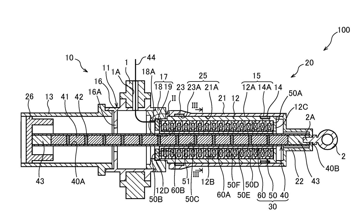
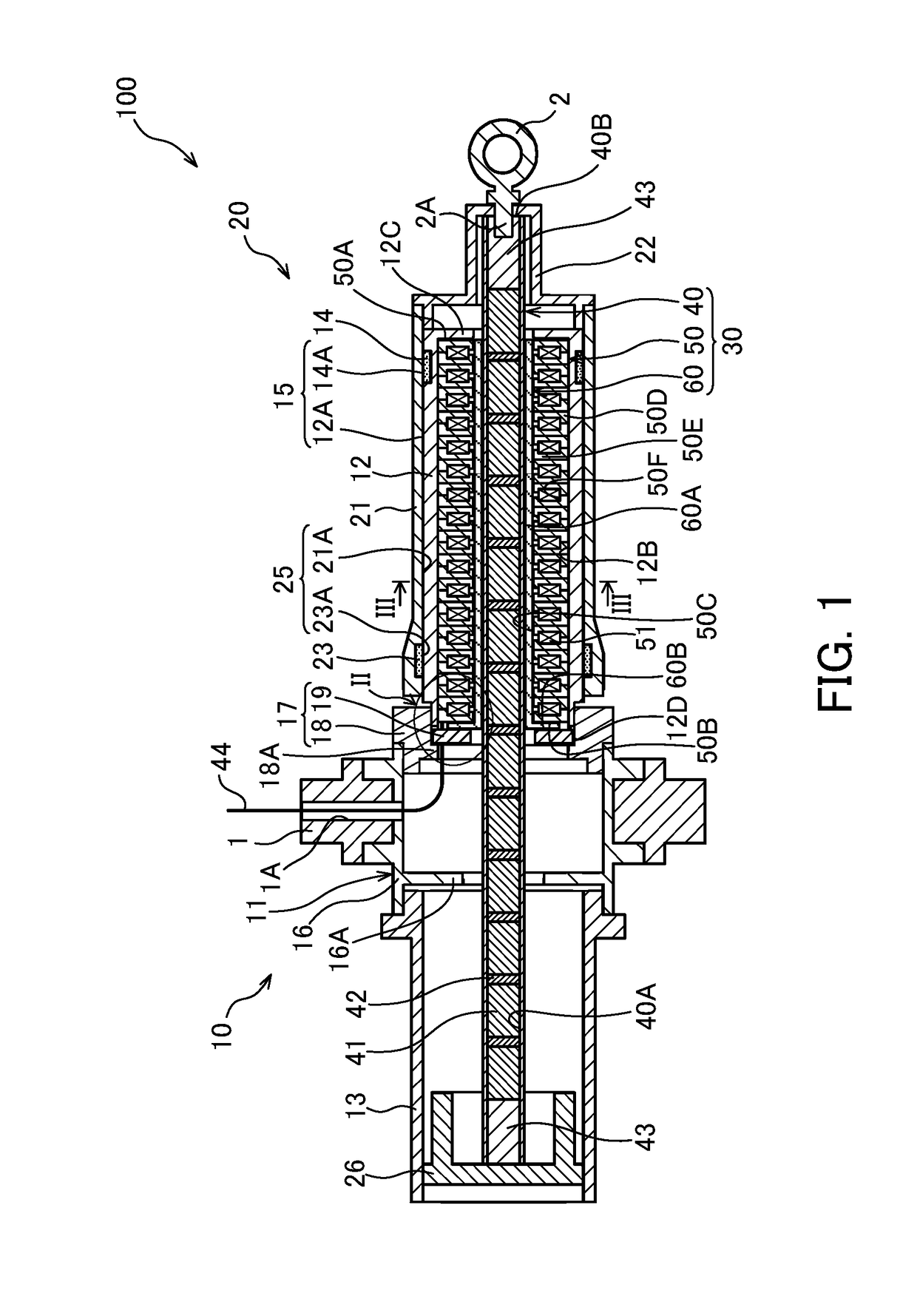
[0011]The following describes a linear motor 30 according to an embodiment of the present invention and a linear actuator 100 having the linear motor 30 with reference to FIG. 1.

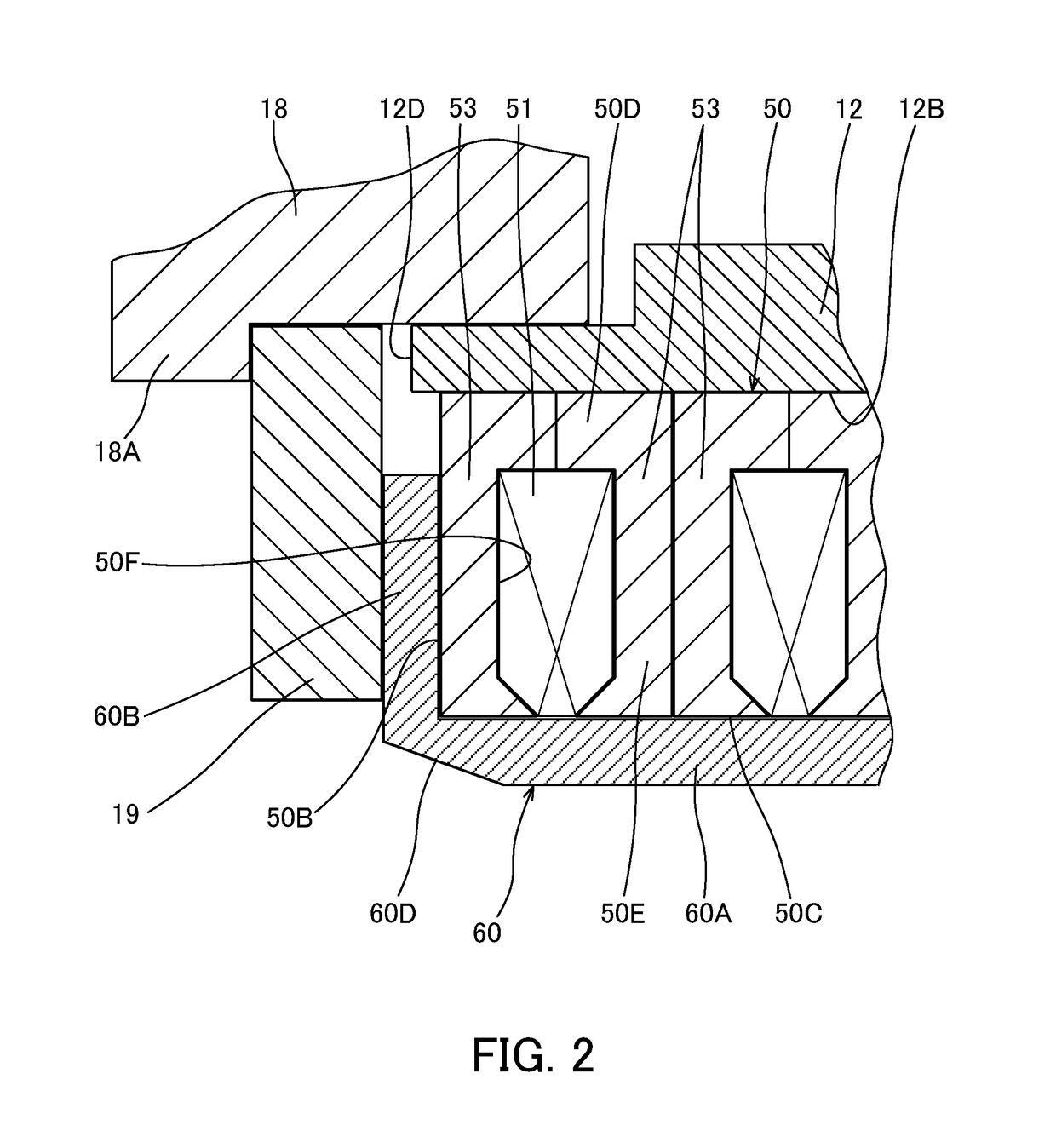
[0012]The linear motor 30 is a driving source for the linear actuator 100, and includes a hollow cylindrical core 50, a cylindrical tubular shaft 40, and a sleeve 60. A plurality of coils 51 are arranged at axial intervals at the inner circumferential side of the core 50. A plurality of permanent magnets 41 are arranged at axial intervals in the shaft 40. The shaft 40 is axially movable inside the core 50. The sleeve 60 is formed from a non-magnetic element, and disposed between the core 50 and the shaft 40 over the substantially entire length of the core 50.

[0013]The linear actuator 100 includes a first tube 10 that is fixed to the core 50 of the linear motor 30, and a second tube 20 that is slidably mounted on an outer circumference of the first tube 10 and is fixed to the shaft 40 of the linear motor 30.

[...


PUM


Abstract

A linear motor includes a hollow cylindrical core, a shaft having a shape of a cylindrical tube, and a sleeve. A plurality of coils are arranged at axial intervals at the inner circumferential side of the core. A plurality of permanent magnets are arranged at axial intervals in the shaft. The shaft is axially movable inside the core. The sleeve is formed from a non-magnetic element, and disposed between the core and the shaft over the entire length of the core.

Description

TECHNICAL FIELD[0001]The present invention relates to a linear motor that is extended and contracted axially by an electromagnetic force, and to a linear actuator having the linear motor.BACKGROUND ART[0002]JP 2005-204449A describes a linear motor that includes a core having a plurality of coils, and a shaft having a plurality of permanent magnets. The shaft moves axially relative to the core when a current is supplied to the coils. The linear motor disclosed in JP 2005-204449A also includes sleeves that are disposed at both axial ends of the core. Between the two sleeves that are disposed at both ends of the core, a gap corresponding to the thickness of the sleeves is present between the shaft and the core. This prevents the core from coming into contact with and sticking to the shaft.SUMMARY OF INVENTION[0003]If the gap between the shaft and the core varies in a circumferential direction of the shaft, the force that pulls the shaft and the core toward each other increases in areas...

Claims


Application Information

Patent Timeline
Patent Type & Authority Applications(United States)
IPC IPC(8): H02K41/03
CPCH02K41/031H02K2207/03H02K41/03H02K41/02
Inventor SATOU, KOUSUKEKANO, YOSHIAKI
Owner KYB CORP
Learn More