
Device for the contactless three-dimensional inspection of a mechanical component with toothing

a three-dimensional inspection and mechanical component technology, applied in measurement devices, caliper-like sensors, instruments, etc., can solve the problems of discontinuous inspection process that needs relatively long inspection time, not optimal method, and visual inspection of components that responds neither to high production rate nor quality requirements

Active Publication Date: 2018-09-06
DWFRITZ AUTOMATION INC
View PDF0 Cites 8 Cited by
  • Summary
  • Abstract
  • Description
  • Claims
  • Application Information

AI Technical Summary

Benefits of technology

The patent describes a device that can scan the teeth on a component to inspect them. The device can scan the teeth on different levels of the component simultaneously, which saves time. This makes it easy to inspect other parts of the component and determine its main axis. The device can be attached to a laser measurement module for easy inspection.

Problems solved by technology

However, the visual inspection of the components responds neither to high production rates nor to quality requirements in certain industrial fields, especially the aeronautical and automotive sectors where certain defects remain difficult to identify with the naked eye.
Mechanical sensing solutions also require a discontinuous inspection process that needs relatively lengthy inspection time.
In addition, components with toothing generally have a complex shape (the toothing elements may have a particular shape and inclination relative to the axis of the particular component for example) requiring the use of separate machines to enable the inspection of all the dimensional characteristics of these components, and this is not an optimal method.
In addition, present-day contactless inspection systems cannot be used to achieve the precision and rates (speeds) dictated by the manufacturing sector.

Method used


Image

  • Device for the contactless three-dimensional inspection of a mechanical component with toothing
  • Device for the contactless three-dimensional inspection of a mechanical component with toothing
  • Device for the contactless three-dimensional inspection of a mechanical component with toothing

Examples


Embodiment Construction

[0047]In all the figures of the present document, the identical elements and steps are designated by one and the same numerical reference.

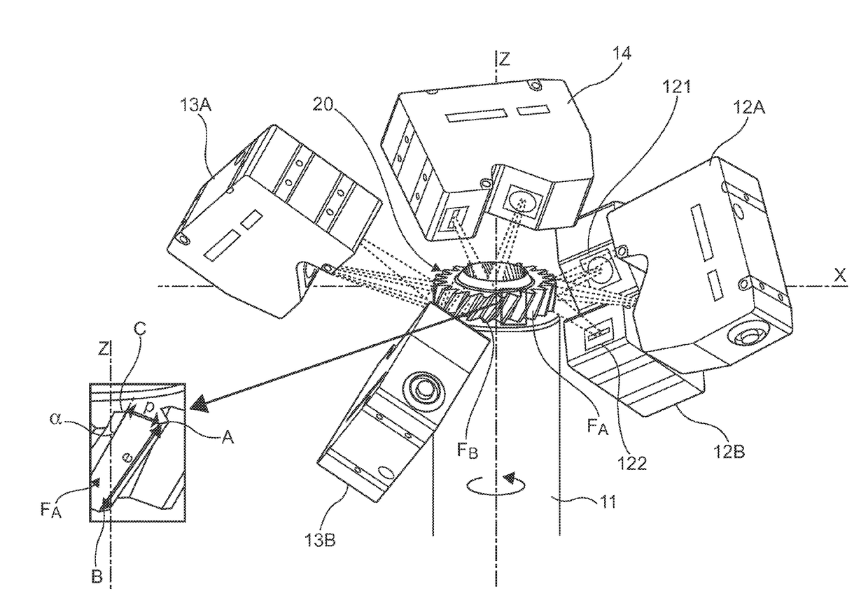
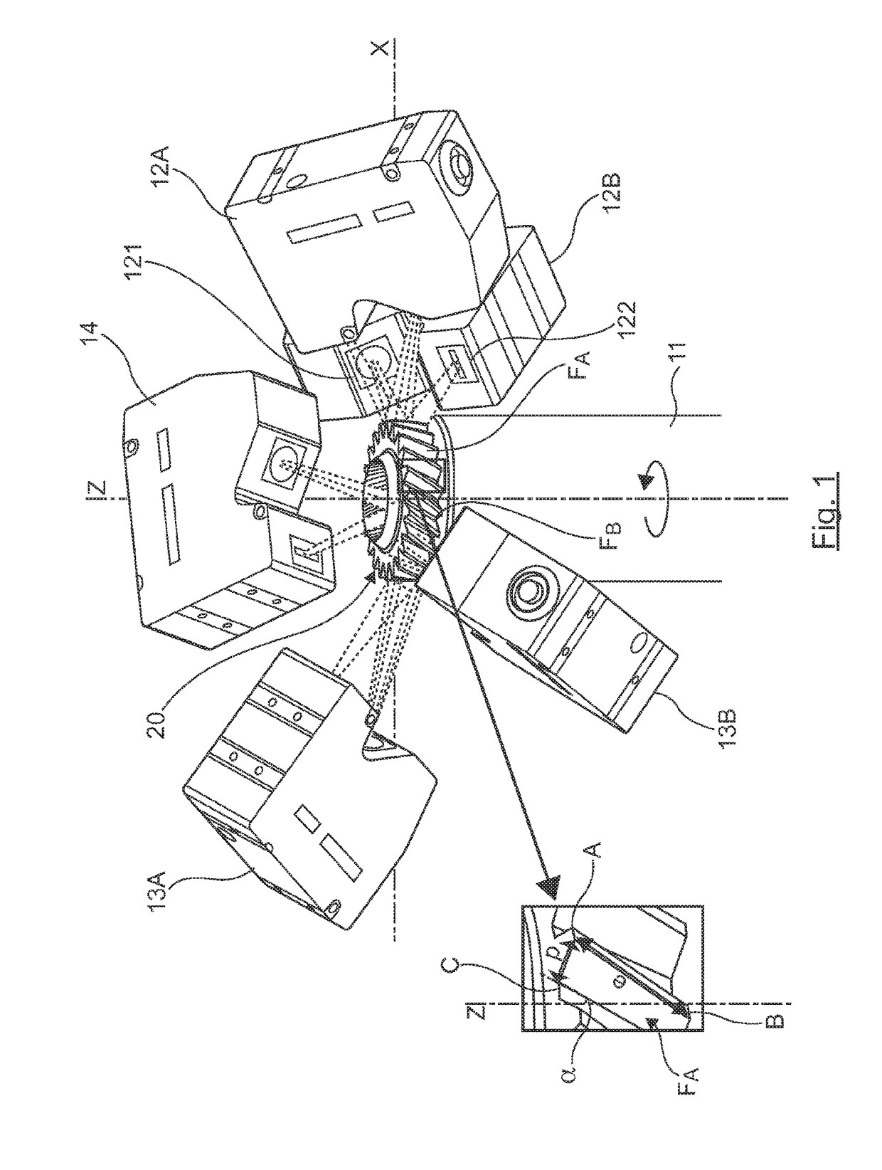
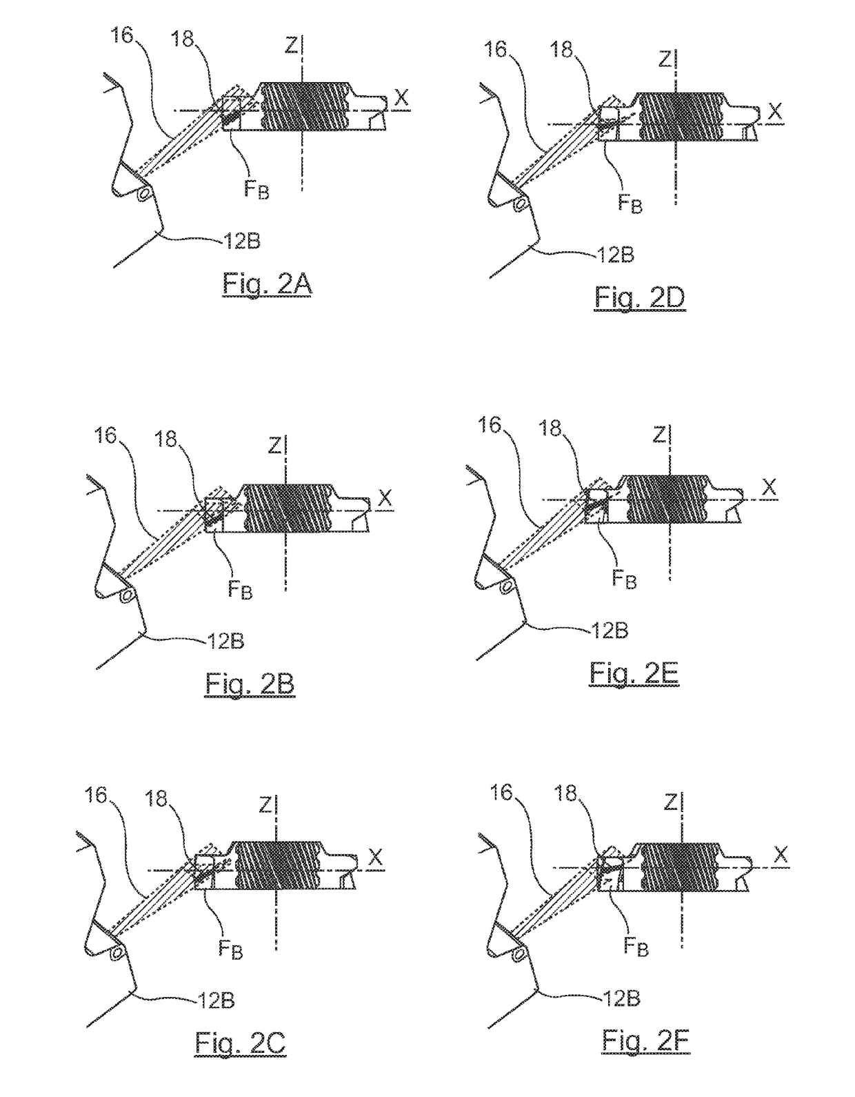
[0048]Referring to FIGS. 1, 2A to 2D, we describe the structure and working of a contactless three-dimensional inspection device 10 according to one particular embodiment of the invention, adapted to the inspection of circular mechanical components with toothing taking the form of a toothed wheel (or pinion gear) 20.

[0049]The inspection device 10 comprises, in the embodiment illustrated in FIG. 1, an object-holder 11 mounted rotationally mobile relative to a frame (not illustrated in the figure). The object-holder 11 holds the toothed wheel 20 to be inspected within the device. The object-holder 11 cooperates with the system used to drive the object-holder in rotation, the unit forming means for the rotational driving of the toothed wheel according to the invention.

[0050]In general, a toothed wheel 20 has a main rotation axis Z and a radial axis X...


PUM


Abstract

An inspection device for contactless three-dimensional inspection of a circular, mechanical component with toothing having a main axis of rotation. The device is configured to scan the teeth by at least one first pair of laser measurement modules and rotationally drive the component about the main axis relative to the laser measurement modules. The device then rebuilds a virtual three-dimensional representation of the component using data coming from said scanning and performs a dimensional inspection using the three-dimensional representation. Each pair of modules includes a first module oriented towards a first face of a tooth and a second module oriented towards a second face of a tooth. The modules are oriented relative to the component so that during a rotation of the component, the laser measurement modules scan the first and second faces of each tooth throughout their thickness and depth.

Description

1. CROSS-REFERENCE TO RELATED APPLICATIONS[0001]This Application is a Continuation-in-Part application of International Application No. PCT / EP2016 / 076337, filed Nov. 2, 2016, the content of which is incorporated herein by reference in its entirety, and published as WO 2017 / 076854 on May 11, 2017, not in English.2. FIELD OF THE INVENTION[0002]The field of the invention is that of the dimensional measurement of mechanical components with toothing.[0003]The invention relates more particularly to a device for the contactless, three-dimensional inspection of a mechanical component with toothing (i.e. with a set of teeth) such as a toothed wheel, a toothed pinion gear or a toothed shaft for example.[0004]Here below in the description, the term “mechanical component with toothing” is used to cover all elements and components that could form part of a gearing or of a gearing system, a pinion-gear transmission, a rack-and-gear transmission or the like. The term “gear-toothing” is understood ...

Claims


Application Information

Patent Timeline
IPC IPC(8): G01B11/24G01B11/02G01B11/06
CPCG01B11/2416G01B11/024G01B11/06G01B11/245G01B2210/44
Inventor LE NEEL, DIDIER
Owner DWFRITZ AUTOMATION INC
Learn More