Wind energy installation and method for controlling a cooling of a wind energy installation
a technology for wind energy installations and wind energy, applied in sustainable buildings, mechanical equipment, machines/engines, etc., can solve the problems of low efficiency, high cost, and low efficiency of wind energy installations, and achieve the effects of reducing the risk of loss, and reducing the cost of installation
- Summary
- Abstract
- Description
- Claims
- Application Information
AI Technical Summary
Benefits of technology
Problems solved by technology
Method used
Image

Examples
first embodiment
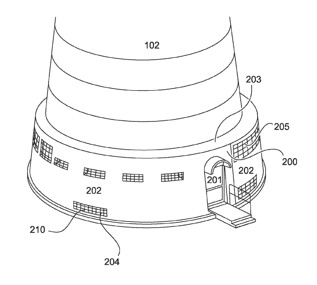
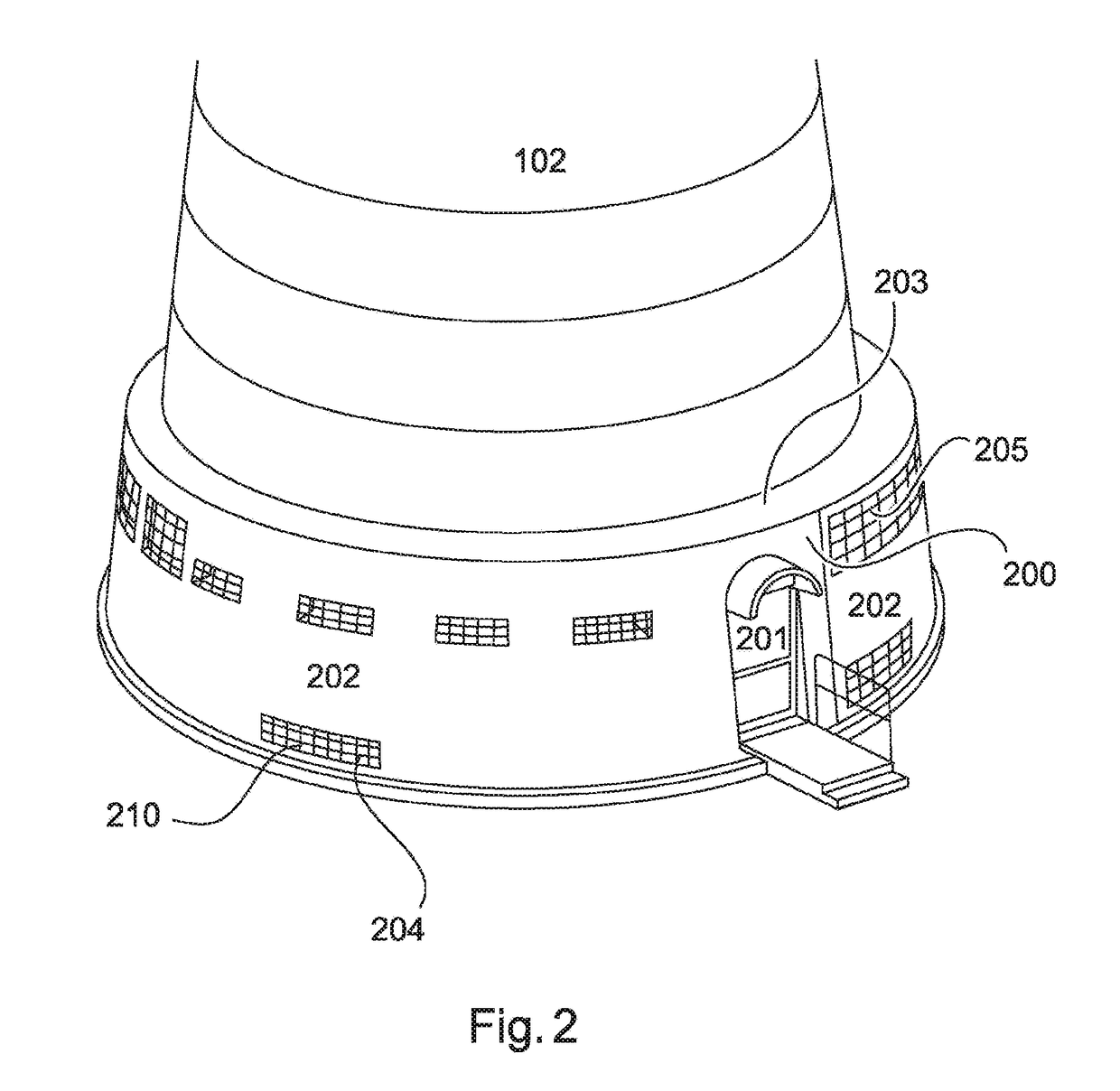
[0042]FIG. 2 shows a diagrammatic view of a lower region of a tower of a wind power installation according to a The first cooling unit 200 has a wall 202 and a roof 203 and preferably completely surrounds the tower 102. As an alternative thereto however the first cooling unit 200 may also only partially surround the tower 102. The first cooling unit 200 has a plurality of lower openings 204 and a plurality of upper openings 205 in the wall 202. The upper openings can also be provided in the roof 203 of the first cooling unit. The first cooling unit also has at least one door 201.
[0043]FIG. 3 shows a diagrammatic partial section of a tower of a wind power installation according to the first embodiment. The first cooling unit 200 has a wall 202 having a plurality of lower openings 204 and a plurality of upper openings 205. The wall 202 is at a spacing relative to the wall 102a of the tower 102. A plurality of heat exchangers 210 is provided between the tower wall 102a and the wall 20...
second embodiment
[0047]FIG. 4 shows a diagrammatic view of a first cooling unit of a wind power installation according to a FIG. 4 in particular shows only the first cooling unit 200. The first cooling unit 200 has a wall 202, a plurality of lower openings 204, a plurality of upper openings 205 and a plurality of heat exchangers 210. Optionally fans 220 can be respectively arranged under the heat exchangers 210. Accordingly cool air can be sucked in by the fans 220 by way of the lower openings 204, guided past the heat exchanger 210 (being heated there) and discharged by way of the upper openings 205. A cooling agent in the heat exchangers 210 can be cooled by that air flow.
[0048]FIG. 5 shows a cross-section of a lower region of a tower of the wind power installation. The wall 202 of the first cooling unit 200 is disposed at a spacing relative to the wall 102a of the tower segment 102. A plurality of heat exchangers 210 can be provided in the region between the tower wall 102a and the wall 202 of t...
third embodiment
[0057]The wind power installation of the third embodiment has a cooling control unit 300. The cooling control unit 300 is coupled both to the first cooling unit 200, 210 and also to the second cooling unit (fan 100a). The control unit 300 can also receive operating parameters of the wind power installation like for example the temperature of the generator, a temperature of the transformer, a temperature of the power cabinet, an outside temperature and so forth, and appropriately control operation of the first and second cooling units. In a first mode of operation of the cooling control unit 300 only the second cooling unit is controlled, by controlling the speed of rotation of the fan 100a. The first cooling unit 200 can be deactivated in that case. In a second mode of operation only the first cooling unit 200 is activated but not the second cooling unit 100a. In a third mode of operation both the first and also the second cooling units 100a, 200 are activated. The cooling control u...
PUM
 Abstract
Description
Claims
Application Information
 - R&D
- Intellectual Property
- Life Sciences
- Materials
- Tech Scout
- Unparalleled Data Quality
- Higher Quality Content
- 60% Fewer Hallucinations
Browse by: Latest US Patents, China's latest patents, Technical Efficacy Thesaurus, Application Domain, Technology Topic, Popular Technical Reports.
© 2025 PatSnap. All rights reserved.Legal|Privacy policy|Modern Slavery Act Transparency Statement|Sitemap|About US| Contact US: help@patsnap.com