
Displacement directed tessellation

a tessellation and displacement technology, applied in the field of computer graphics, can solve problems such as the current method of subdivision suffering from exponential memory growth

Active Publication Date: 2018-08-23
SONY COMPUTER ENTERTAINMENT INC
View PDF2 Cites 3 Cited by
  • Summary
  • Abstract
  • Description
  • Claims
  • Application Information

AI Technical Summary

Benefits of technology

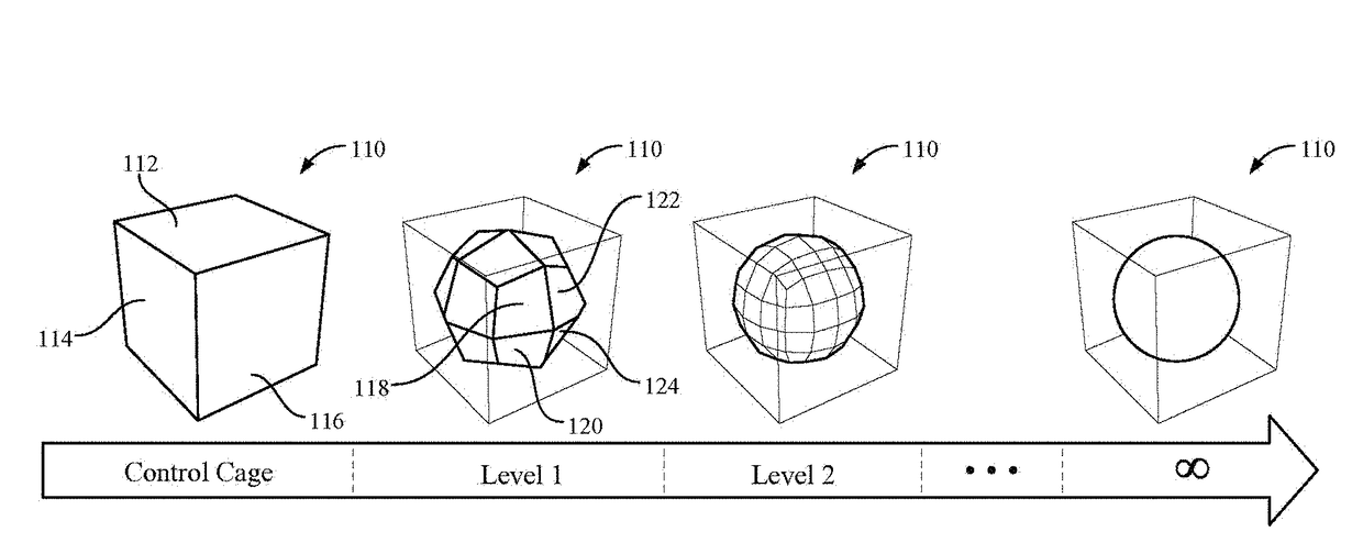
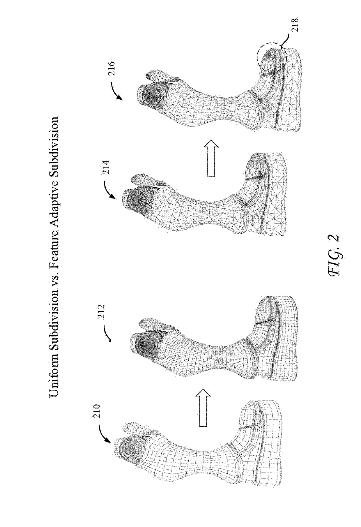
The present technology is about a system and method for rendering computer graphics using displacement directed tessellation. The technology solves the problem of exponential memory growth in computer graphics by creating a displacement map for a plurality of surfaces and initiating a tessellation process. The tessellation density of a first set of surfaces is modified based on the displacement map, and the tessellation factor scale for each surface is increased or decreased accordingly. The technology also includes a pre-process for scaling up or down tessellation factors on patches that require high or low tessellation factors to accurately represent the displaced surface. The technology can be practiced without specific details and is not limited to the examples provided.

Problems solved by technology

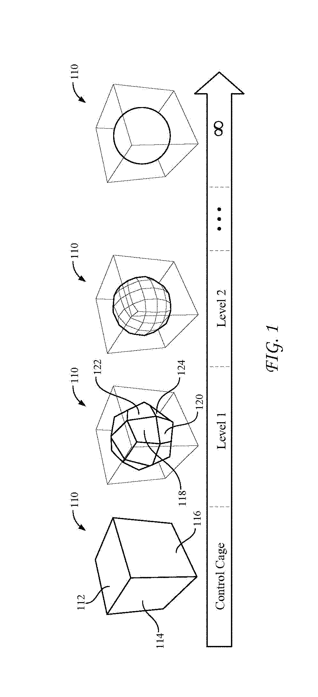
However, current methods of subdivision suffer from exponential memory growth.

Method used


Image

  • Displacement directed tessellation
  • Displacement directed tessellation
  • Displacement directed tessellation

Examples


example embodiments

[0015]The following presents a simplified summary of one or more embodiments in order to provide a basic understanding of the present technology. This summary is not an extensive overview of all the contemplated embodiments of the present technology, and is intended to neither identify key or critical elements of all examples nor delineate the scope of any or all aspects of the present technology. Its sole purpose is to present some concepts of one or more examples in a simplified form as a prelude to the more detailed description that is presented later.

[0016]In an aspect, a method for rendering computer graphics using displacement directed tessellation samples a displacement map for a plurality of surfaces, such as sampling the displacement map in one or more pre-processes and then determining a set of scales per patch. A patch can be a subset of vertices and / or connected vertices on a mesh (e.g., can define a surface or subsurface on the mesh). The pre-process enables scaling up ...


PUM


Abstract

Systems, methods, and devices are disclosed for rendering computer graphics. In various embodiments, a displacement map is created for a plurality of surfaces and a tessellation process is initiated. It is determined that the tessellation density of a first set of surfaces and a second set of surfaces should be modified based on the displacement map. Based on the displacement map, a tessellation factor scale for each surface of the first set of surfaces is increased and a tessellation factor scale for each surface of the second set of surfaces is decreased, respectively.

Description

CROSS-REFERENCE TO RELATED APPLICATIONS[0001]The present application claims the priority benefit of U.S. provisional application 62 / 462,889 filed on Feb. 23, 2017, the disclosure of which is incorporated herein by reference.TECHNICAL FIELD[0002]This application relates to computer graphics, and more particularly to a system and method for rendering computer graphics.BACKGROUND[0003]Highly detailed surface models are becoming commonplace in the area of computer graphics, in part due to three-dimensional scanning technologies. Typically, these models are represented as dense triangle meshes.[0004]Subdivision surfaces have become popular recently in graphical modeling, animation, and computer aided design (CAD) / modeling (CAM) because of their stability in numerical computation, simplicity in coding, and most importantly their capability in modeling / representing complex shapes of arbitrary topology. However, current methods of subdivision suffer from exponential memory growth.BRIEF DESC...

Claims


Application Information

Patent Timeline
Patent Type & Authority Applications(United States)
IPC IPC(8): G06T17/20G06T3/40
CPCG06T17/20G06T3/40G06T2210/36
Inventor DOOLITTLE, JOHNMURAKAWA, JUNHO, CHRISTOPHER
Owner SONY COMPUTER ENTERTAINMENT INC
Learn More