
Methods and apparatus for reference signal design for interference cancellation

a reference signal and interference cancellation technology, applied in the field of reference signal design, can solve the problems of affecting the performance of downlink and uplink, transmission from the base station may encounter interference, and transmission from the ue may encounter interferen

Active Publication Date: 2018-08-16
QUALCOMM INC
View PDF1 Cites 18 Cited by
  • Summary
  • Abstract
  • Description
  • Claims
  • Application Information

AI Technical Summary

Benefits of technology

The present invention provides a method and apparatus for wireless communication that can improve the efficiency and reliability of wireless communication networks. Specifically, the invention provides a method for a base station to determine the optimal demodulation reference signal (DMRS) sequence or location pattern for its transmissions based on the transmission characteristics of the base station. The base station can then transmit the determined DMRS sequence or location pattern to a user equipment (UE) for interference cancellation. This allows for more effective interference cancellation and improved wireless communication performance.

Problems solved by technology

On the downlink, a transmission from the base station may encounter interference due to transmissions from neighbor base stations or from other wireless radio frequency (RF) transmitters.
On the uplink, a transmission from the UE may encounter interference from uplink transmissions of other UEs communicating with the neighbor base stations or from other wireless RF transmitters.
This interference may degrade performance on both the downlink and uplink.
Therefore, inefficient transmissions of reference signals by the neighboring base station may affect estimation of transmission characteristics of the neighboring base station by the UE.
As a result, interference cancellation by the UE for transmissions from the neighboring base stations may suffer.

Method used


Image

  • Methods and apparatus for reference signal design for interference cancellation
  • Methods and apparatus for reference signal design for interference cancellation
  • Methods and apparatus for reference signal design for interference cancellation

Examples


Embodiment Construction

[0008]The following summarizes some aspects of the present disclosure to provide a basic understanding of the discussed technology. This summary is not an extensive overview of all contemplated features of the disclosure, and is intended neither to identify key or critical elements of all aspects of the disclosure nor to delineate the scope of any or all aspects of the disclosure. Its sole purpose is to present some concepts of one or more aspects of the disclosure in summary form as a prelude to the more detailed description that is presented later.

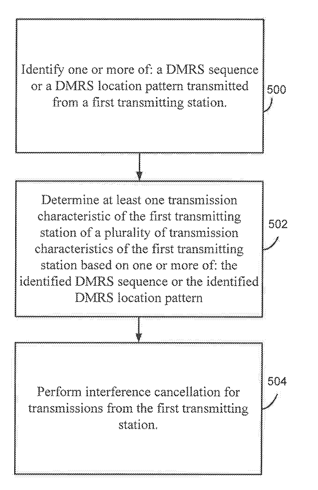
[0009]In one aspect of the disclosure, a method for wireless communication is provided. For example, a method can include determining, by a base station based on at least one transmission characteristic of the base station of a plurality of transmission characteristics of the base station, one or more of a demodulation reference signal (DMRS) sequence including at least one DMRS symbols or a DMRS location pattern including a set of resou...


PUM


Abstract

Methods and apparatus for reference signal design are provided. In some aspects, a base station determines one or more of: a demodulation reference signal (DMRS) sequence or a DMRS location pattern, based on at least one of a plurality of transmission characteristics, and transmits one or more of the determined DMRS sequence or the determined DMRS location pattern. In further aspects, a user equipment identifies one or more of: a demodulation reference signal (DMRS) sequence or a DMRS location pattern from a base station, determines at least one of a plurality of transmission characteristics of the first base station based on one or more of: the identified DMRS sequence or the identified DMRS location pattern, and performs interference cancellation for transmissions from the base station.

Description

CROSS-REFERENCE TO RELATED APPLICATIONS[0001]This application claims the benefit of U.S. Provisional Patent Application No. 62 / 459,552, entitled, “METHODS AND APPARATUS FOR REFERENCE SIGNAL DESIGN FOR INTERFERENCE CANCELLATION,” filed on Feb. 15, 2017, the disclosure of which is hereby incorporated by reference herein in its entirety as if fully set forth below and for all applicable purposes.TECHNICAL FIELD[0002]Aspects of the present disclosure relate generally to wireless communication systems, and more particularly, to reference signal design. Certain embodiments of the technology discussed below can improve estimation of neighboring cell transmission characteristics and facilitate interference cancellation.INTRODUCTION[0003]Wireless communication networks are widely deployed to provide various communication services such as voice, video, packet data, messaging, broadcast, and the like. These wireless networks may be multiple-access networks capable of supporting multiple users ...

Claims


Application Information

Patent Timeline
IPC IPC(8): H04L27/26H04L5/00H04W72/04H04J11/00
CPCH04L27/2613H04L5/0073H04J11/0053H04W72/0426H04L5/0035H04L27/262H04L5/0051H04J11/005H04L5/0048H04L27/261H04W72/27
Inventor AKKARAKARAN, SONYLUO, TAOCHENDAMARAI KANNAN, ARUMUGAMJOHN WILSON, MAKESH PRAVIN
Owner QUALCOMM INC
Learn More