
Turbocharger

a technology of turbocharger and cylinder head, which is applied in the direction of combustion engines, machines/engines, engine fuctions, etc., can solve the problems of noise generation or wear of sliding parts, elastic members subjected to fatigue and weakening, and disturbance of the flow of exhaust gas

Active Publication Date: 2018-08-16
TOYOTA JIDOSHA KK
View PDF3 Cites 5 Cited by
  • Summary
  • Abstract
  • Description
  • Claims
  • Application Information

AI Technical Summary

Benefits of technology

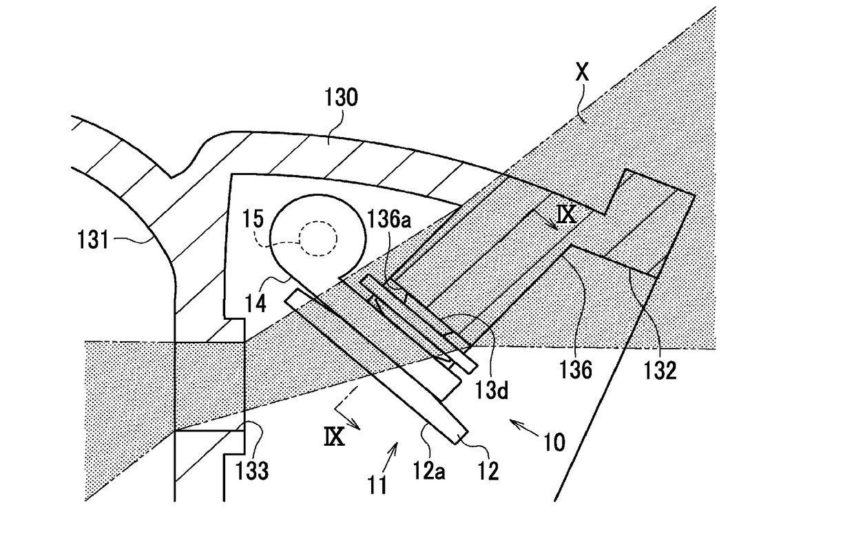
The present invention aims to reduce vibration and wear of the valve body, and to suppress disturbance of the flow of exhaust gas caused by the collision of the valve body with the stopper when the waste gate valve is open. The technical effects of this invention include reducing vibration of the valve body, suppressing wear of the valve stem, and suppressing fatigue and weakening of the elastic member. Additionally, the invention shields the space between the waste gate port and the stopper by the valve plate, preventing direct collision of the exhaust gas with the stopper and reducing disturbance of the flow of exhaust gas.

Problems solved by technology

The vibration results in noise generation or wearing of a sliding part.
However, the elastic member is subjected to fatigue and weakening as the vibration continues to be input to the elastic member.
When the stopper is disposed at a position with which the exhaust gas blown out from the waste gate port directly collides, disturbance arises in the flow of the exhaust gas due to the collision with the stopper.

Method used


Image

  • Turbocharger
  • Turbocharger
  • Turbocharger

Examples


Embodiment Construction

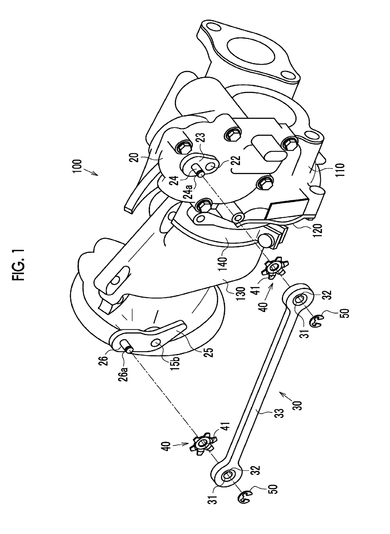
[0033]Hereinafter, an embodiment of a turbocharger will be described with reference to FIGS. 1 to 9. As illustrated in FIG. 1, a turbocharger 100 is configured as a combination of a compressor housing 110, a bearing housing 120, and a turbine housing 130. The compressor housing 110 is a housing accommodating a compressor wheel. The turbine housing 130 is a housing accommodating a turbine wheel. The bearing housing 120 is a housing supporting a connecting shaft connecting the compressor wheel and the turbine wheel to each other.

[0034]The bearing housing 120 is fastened to the compressor housing 110 by a bolt. The turbine housing 130 is assembled to the bearing housing 120 by a clamp 140.

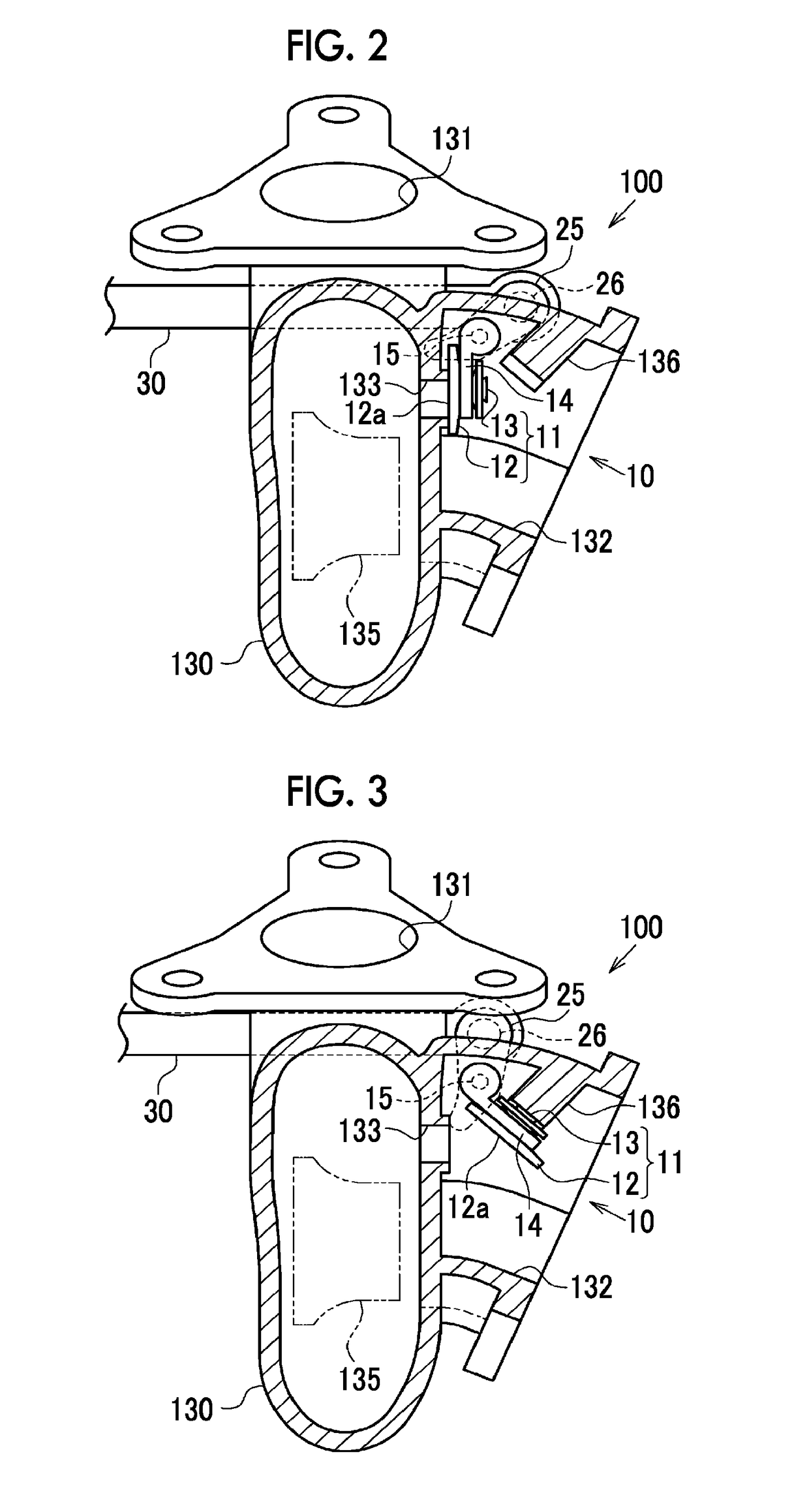
[0035]As illustrated in FIG. 2, a turbine wheel 135 is accommodated in the turbine housing 130 and a scroll passage 131 extending to surround the turbine wheel 135 is formed in the turbine housing 130. Exhaust gas blown to the turbine wheel 135 through the scroll passage 131 is discharged from the tur...


PUM


Abstract

A turbocharger includes a turbine wheel, a turbine housing including a waste gate port allowing exhaust gas to flow by bypassing the turbine wheel, and a waste gate valve configured to open and close the waste gate port. The waste gate valve is configured such that a valve body including a valve plate configured to close the waste gate port by abutting against the turbine housing and a valve stem is tilted with respect to a swing arm. A stopper abutting against the valve body when an abutting surface of the valve plate is apart from the turbine housing and the waste gate port is in an open state is disposed in the turbine housing.

Description

INCORPORATION BY REFERENCE[0001]The disclosure of Japanese Patent Application No. 2017-025053 filed on Feb. 14, 2017 including the specification, drawings and abstract is incorporated herein by reference in its entirety.BACKGROUND1. Technical Field[0002]The present disclosure relates to a turbocharger provided with a waste gate valve.2. Description of Related Art[0003]Japanese Unexamined Patent Application Publication No. 2012-67698 (JP 2012-67698 A) discloses a turbocharger provided with a waste gate valve configured to open and close a waste gate port disposed in a turbine housing when a swing arm supporting a valve body rotates as a result of rotation of a shaft passing through the turbine housing.[0004]In the waste gate valve disclosed in JP 2012-67698 A, the valve body is attached to the swing arm via an elastic member and the valve body can be tilted with respect to the swing arm.SUMMARY[0005]In the waste gate valve in which the valve body is mounted on and can be tilted with ...

Claims


Application Information

Patent Timeline
Patent Type & Authority Applications(United States)
IPC IPC(8): F01D17/10F01D15/08F02B37/18
CPCF01D17/105F01D15/08F02B37/186F05D2220/40F05D2260/606F02B37/183Y02T10/12
Inventor NAKAMURA, NAOTO
Owner TOYOTA JIDOSHA KK
Learn More