Methods and systems for electrophysiology ablation gap analysis

a gap analysis and electrophysiology technology, applied in the field of methods and systems for conducting electrophysiology ablation, can solve the problems of residual propagation of the electrical pathways causing the arrhythmia, inability to perform ablation treatment, and inability to achieve the effect of the duration of the ep ablation procedure, reducing the risk of complications

Active Publication Date: 2018-08-09
GENERAL ELECTRIC CO
View PDF2 Cites 7 Cited by
  • Summary
  • Abstract
  • Description
  • Claims
  • Application Information

AI Technical Summary

Benefits of technology

The patent describes a method for predicting and identifying gaps between electrophysiology ablation points recorded from a completed electrophysiology ablation procedure. This helps an operator locate and mitigate possible gap locations via additional ablation applications or diagnosis. The method reduces the risk of complications, the duration of the EP ablation procedure, and additional equipment and technology costs associated with digital camera image processing, NADH fluorescence, and the like. It also allows for a more reliable and accurate identification of gaps between EP ablation points, accounting for ablation tolerance variables and complexities in tissue topography and real-time movement of the tissue during the EP ablation. The method can be easily and flexibly retrofitted to augment existing EP ablation systems and adjusted by the operator to account for a broad range of ablation tolerance variables.

Problems solved by technology

Once the problematic tissue is identified, electrical radiofrequency energy (or other types of energy) are delivered to the heart by way of the catheter to destroy the tissue, thereby blocking and disrupting the electrical pathways responsible for the arrhythmia.
Due to inherent uncertainties associated with factors including catheter positioning, energy delivery, and tissue morphology, the EP tissue ablation treatment can often be inadequate, and residual propagation of the electrical pathways causing the arrhythmia can subsist.
Errors in gap identification can result in a change in the conduction pathway after EP ablation, but without elimination of the underlying condition (e.g. arrhythmia).
Consequently, a relatively high percentage of ablation cases regularly involve patient readmission for follow-up EP ablation procedures, thereby increasing healthcare costs, increasing patient health complication risks, and reducing patient satisfaction.
Furthermore, due to the propensity of follow-up procedures, EP ablation's utility as a permanent cure for cardiac arrhythmia (and other conditions) is limited; instead, patients often rely on EP ablation for repeat treatment and management of their health conditions in order to mitigate risks of complications such as stroke, heart failure, and death, in the case of treating arrhythmia.
Namely, these conventional approaches are invasive, delivering additional devices such as endoscopes and cameras into the patient's body during the EP ablation procedure, which significantly increase the complexity, cost, duration, and risk of complications associated with the EP ablation procedure.
For example, additional catheters may need to be conveyed inside the patient's body in order to accommodate these devices, which can increase a risk of complications and lengthen the duration of the procedure.
Furthermore, additional technology such as NADH excitation, fluorescence sensors, endoscopes, and signal processing thereof is used, raising equipment and capital costs for the procedure.
Further still, factors such as tissue topography, movement of the tissue during the procedure, physician experience, and other sources of uncertainty in the ablation system are not accounted for, thereby reducing a reliability of correctly identifying EP ablation location which may result in gaps and lesion site deficiencies.

Method used


Image

  • Methods and systems for electrophysiology ablation gap analysis
  • Methods and systems for electrophysiology ablation gap analysis
  • Methods and systems for electrophysiology ablation gap analysis

Examples


Embodiment Construction

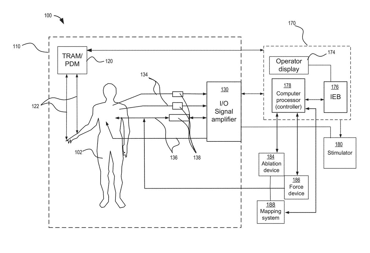
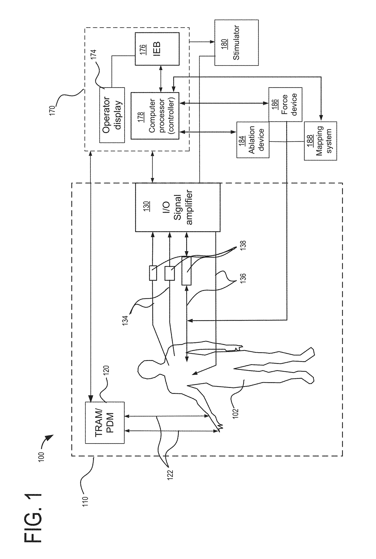
[0018]The following description relates to various embodiments of methods and systems for conducting electrophysiology (EP) ablation.

[0019]In one embodiment, the issues described above may be at least partially addressed by a method of identifying gaps between electrophysiology ablation points, comprising: obtaining a plurality of ablation points recorded from a completed electrophysiology ablation procedure; digitally mapping the plurality of ablation points to an anatomical model corresponding to the completed electrophysiology ablation procedure; calculating ablation gap probability distributions for each of the plurality of ablation points based on ablation tolerance variables associated with each of the plurality of ablation points; and overlaying the ablation gap probability distributions on to the digitally mapped plurality of ablation points on the anatomical model.

[0020]EP ablation involves delivering electrical energy by way of catheter electrodes to various tissue sites w...


PUM


Abstract

A method of identifying gaps between electrophysiology (EP) ablation points may comprise: obtaining a plurality of ablation points recorded from a completed electrophysiology ablation procedure; digitally mapping the plurality of ablation points to an anatomical model corresponding to the completed electrophysiology ablation procedure; calculating ablation gap probability distributions for each of the plurality of ablation points based on ablation tolerance variables associated with each of the plurality of ablation points; and overlaying the ablation gap probability distributions on to the digitally mapped plurality of ablation points on the anatomical model. In this way, ablation gaps may be non-invasively identified prior to patient discharge, thereby allowing for further EP treatment to remove the ablation gaps while reducing readmission rates. Furthermore, by representing ablation points using calculated ablation burn density distributions and ablation gap probabilities, the accuracy of identifying ablation gaps may be increased.

Description

FIELD[0001]Embodiments of the subject matter disclosed herein relate to a methods and systems for conducting electrophysiology ablation.BACKGROUND[0002]Electrophysiology (EP) ablation is an invasive surgical procedure for treating conditions such as cardiac arrhythmia including, but not limited to, atrial fibrillation. Small and flexible catheters conveying electrodes and various instruments are inserted into blood vessels in a patient's body and guided toward the target tissue or organ to be treated. In the case of cardiac ablation, electrodes are guided through the catheters to the heart to measure and diagnose the heart condition, and to identify the tissue causing the arrhythmia. Once the problematic tissue is identified, electrical radiofrequency energy (or other types of energy) are delivered to the heart by way of the catheter to destroy the tissue, thereby blocking and disrupting the electrical pathways responsible for the arrhythmia. EP ablation procedures may also be used ...

Claims


Application Information

Patent Timeline
Patent Type & Authority Applications(United States)
IPC IPC(8): A61B18/00A61B5/00A61B18/12
CPCA61B18/00A61B5/4848A61B2018/00642A61B2018/00577A61B2017/00199A61B18/12A61B2018/00648A61B2018/00666A61B2018/00702A61B2018/00779A61B2018/00797A61B2018/00839A61B2018/00875A61B2034/105
Inventor WARNER, ADRIAN F.SCHNEIDEWEND, DANIEL RICHARD
Owner GENERAL ELECTRIC CO
Why Eureka
Try Eureka