
Engine device

Inactive Publication Date: 2018-08-02
YANMAR POWER TECHNOLOGY CO LTD
View PDF16 Cites 0 Cited by
  • Summary
  • Abstract
  • Description
  • Claims
  • Application Information

AI Technical Summary

Benefits of technology

The present invention is about controlling ignition timing to optimize engine performance. When air is insufficient, multiple steps of ignition timing retard control are implemented to reduce knocking and improve combustion efficiency. This treatment also prevents excessive retarding of ignition timing and ensures a stable operation. The ignition timing is predicted by predicting surplus or shortage of air in the intake manifold, making it suitable for structures such as large engines. Overall, this technology improves engine performance by optimizing ignition timing and combustion efficiency.

Problems solved by technology

However, the exhaust gas of the diesel engine contains a large amount of nitrogen oxide, sulfur oxides, particulate matter, and the like which are harmful substances hindering preservation of the environment.

Method used


Image

  • Engine device
  • Engine device
  • Engine device

Examples


first embodiment

[0055]The following description is based on drawings showing an application of a first embodiment embodying the present invention to an electric power generating mechanism mounted in an electric propulsion ship.

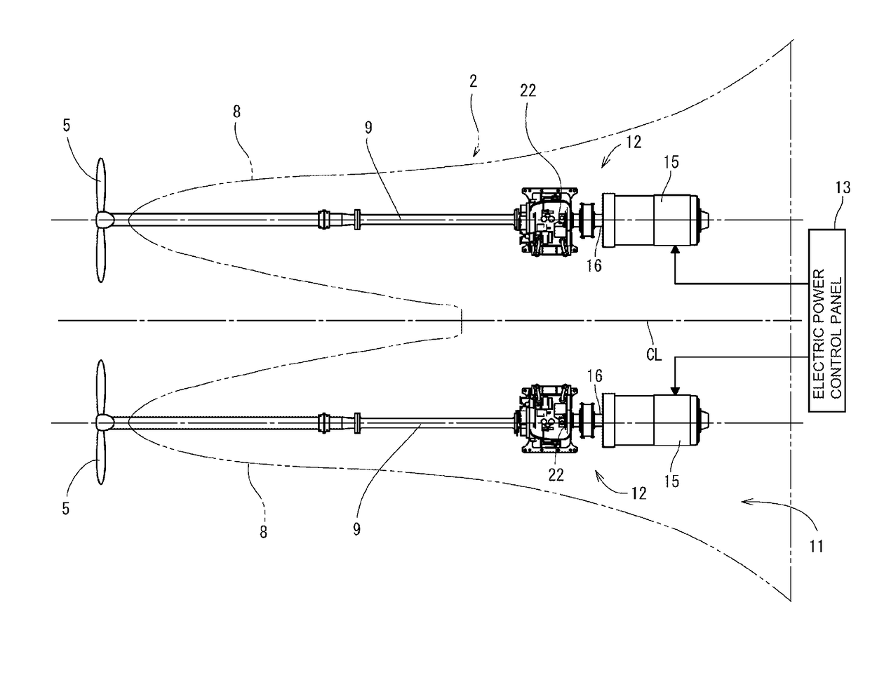
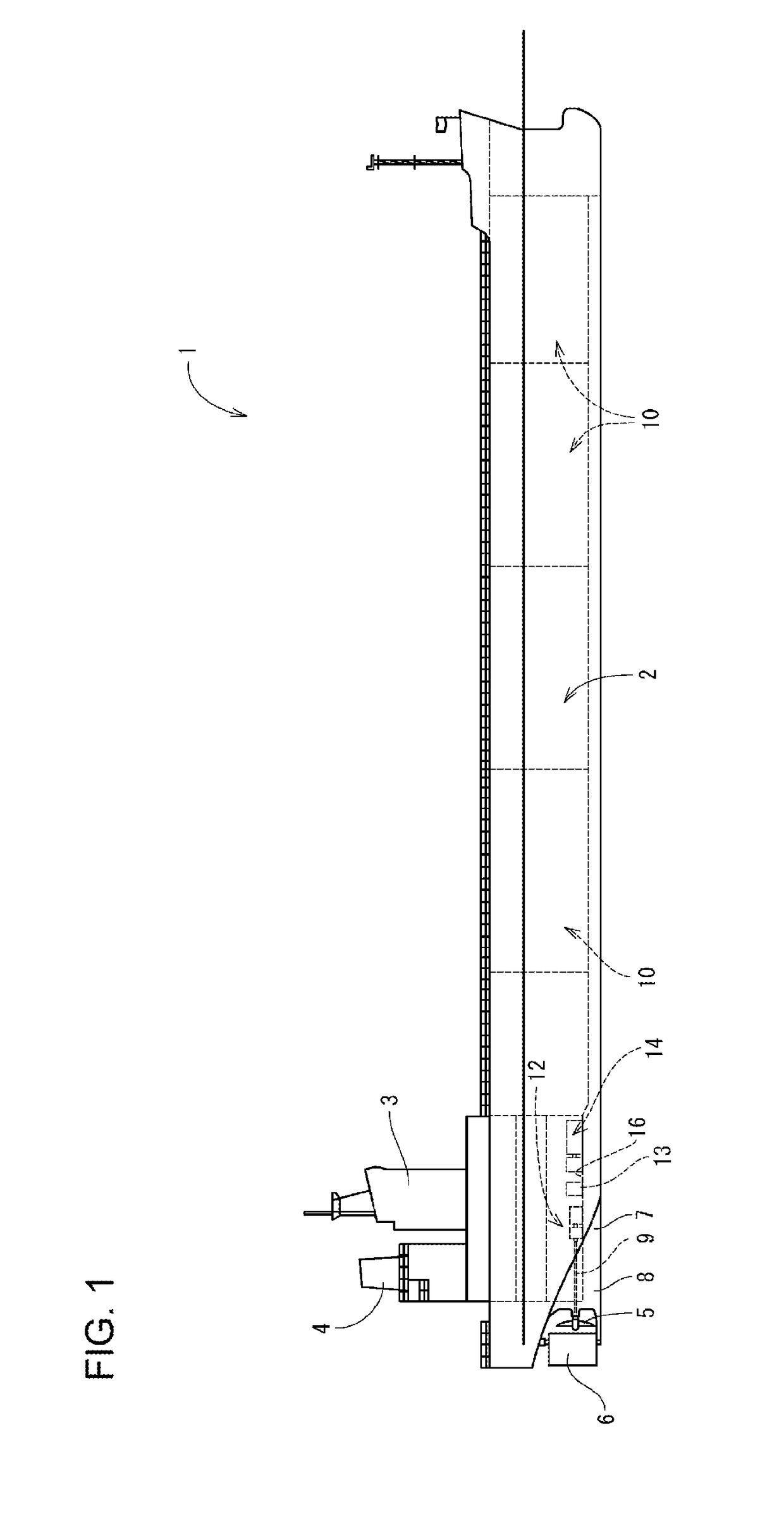
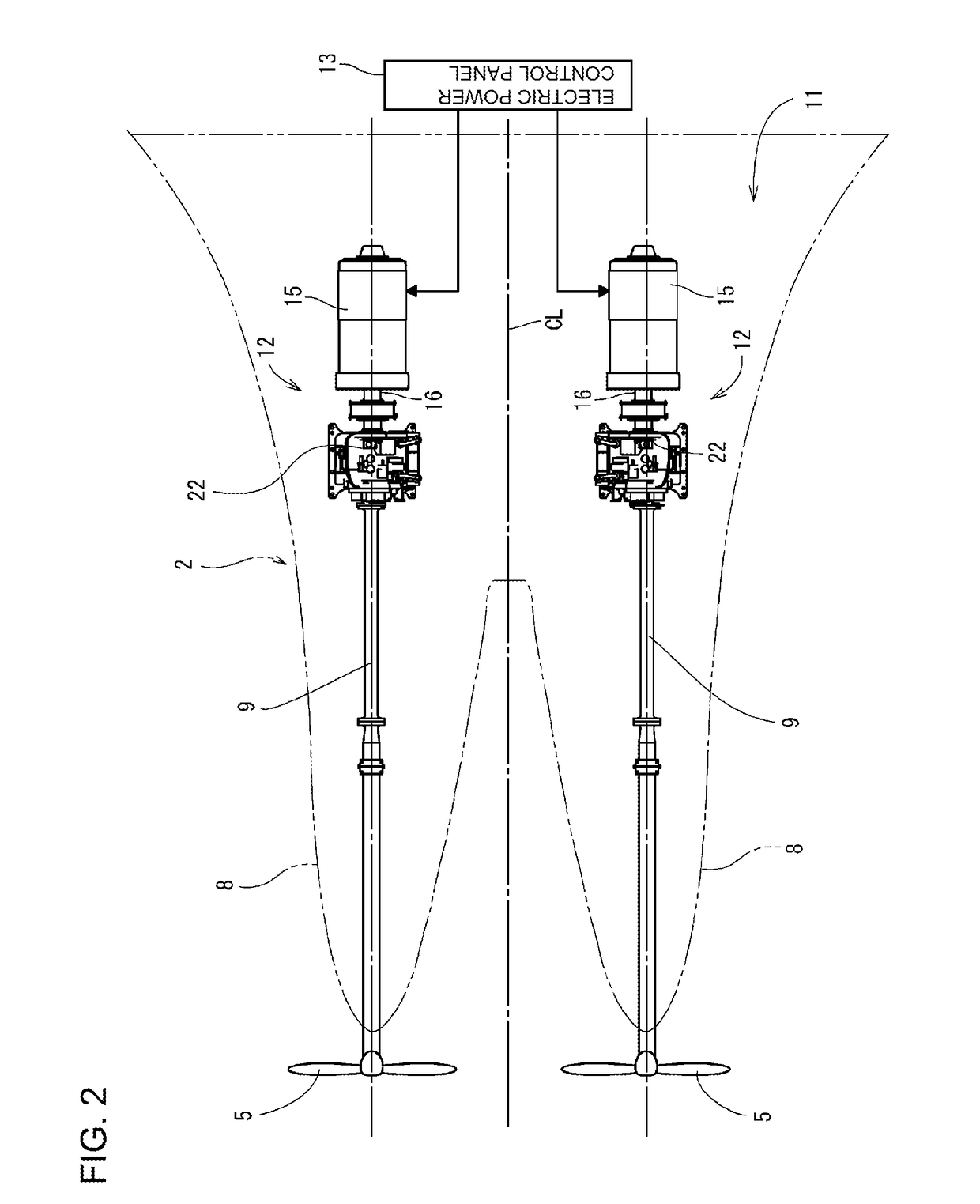
[0056]First, an overview of the ship is described. As shown in FIG. 1 to FIG. 3, the ship 1 of the present embodiment includes: a ship hull 2, a cabin 3 (bridge) provided on the stern side of the ship hull 2, a funnel 4 (chimney) positioned behind the cabin 3, and a pair of propellers 5 and a rudder 6 provided on a lower back portion of the ship hull 2. In this case, a pair of skegs 8 are integrally formed on the ship bottom 7 on the stern side. On each of the skegs 8, a propeller shaft 9 for driving to rotate the propeller 5 is pivotally supported. The skegs 8 are symmetrically formed on the left and right, with respect to the ship hull center line CL (see FIG. 2) which divides the lateral width direction of the ship hull 2. That is, the first embodiment adopts a twin skeg a...

second embodiment

[0131]In the present embodiment, the advance amount and retard amount are set to be constant amount of Δt and varied in multiple steps, as in the setting control of the above-described ignition timing. However, a retard amount of the ignition timing based on the parameter amount for determining the surplus or shortage of the air amount may be stored in advance. The following describes a control operation for the engine device of another embodiment (second embodiment), with reference to FIG. 20.

[0132]As shown in FIG. 20, in the engine device of the second embodiment, the engine controlling device 73 sets the targeted ignition timing Dtm by referring to the target ignition timing map M4, and sets a retard amount ΔDTd by referring to a retardation setting map M5, to ignite the spark plug 82 at an ignition timing DTm+ΔDTd. The target ignition timing map M4 indicates the correlation between the engine load (generator output or engine torque) Ac measured by the load measuring device 19 an...


PUM


Abstract

An engine device including an intake manifold (67) configured to supply air into a cylinder (36) a gas injector (98) configured to mix fuel gas with air supplied from the intake manifold (67) and supply mixed gas to the cylinder (36) and an igniter (79) configured to ignite, in the cylinder (36) premixed fuel obtained by pre-mixing the fuel gas with the air, the engine device further including a controlling unit (73) configured to determine an air amount in the premixed fuel in the cylinder (36) The controlling unit (73) performs in multiple steps retard control of ignition timing by the igniter (79), when the air amount is insufficient, and performs in multiple steps advance control of the ignition timing, when the air amount is.

Description

TECHNICAL FIELD[0001]The present invention relates to an engine device to serve as a drive source, and particularly relates to an engine device configured to rotate an output shaft through combustion of a fuel gas.BACKGROUND ART[0002]Traditionally, diesel engines are used as a drive source of vessels such as tankers or transport ships and onshore power generation facilities. However, the exhaust gas of the diesel engine contains a large amount of nitrogen oxide, sulfur oxides, particulate matter, and the like which are harmful substances hindering preservation of the environment. For this reason, in recent years, gas engines that can reduce the amount of harmful substances generated are becoming prevalent as an alternative engine for diesel engines.[0003]A so-called gas engine that generates power by using a fuel gas such as natural gas supplies a mixed gas obtained by mixing a fuel gas with the air to a cylinder and combust the same (see Patent Literature 1; hereinafter PTL 1). Fur...

Claims


Application Information

Patent Timeline
IPC IPC(8): F02D41/18F02D41/00F02P5/15F02D41/14B63H21/17
CPCF02D41/18F02D41/0027F02P5/15F02D41/144B63H21/17F02D2200/0406F02D2200/10F02M21/0248F02B61/04B63B2755/00F02D41/0025F02P5/1523F02D19/02F02D45/00Y02T10/40F02D37/02F02P5/1502Y02T10/30
Inventor HAGIWARA, RYOICHIYAMAGISHI, OSAMUIKEDA, NAOYA
Owner YANMAR POWER TECHNOLOGY CO LTD
Learn More