
Touch assembly, display panel and a method for manufacturing touch assembly

a technology of touch assembly and display panel, applied in the field of display, can solve problems such as bright and dark stripes, and achieve the effect of improving the phenomenon of bright and dark stripes

Active Publication Date: 2018-07-26
BOE TECH GRP CO LTD +1
View PDF0 Cites 3 Cited by
  • Summary
  • Abstract
  • Description
  • Claims
  • Application Information

AI Technical Summary

Benefits of technology

The present patent aims to improve the physical appearance of On-Cell Touch Panels by reducing the display's bright and dark stripes and Moiré fringes. The patent provides a touch assembly, a display panel, and a manufacturing method for that purpose.

Problems solved by technology

However, in contrast to other touch solutions, as far as a product of the type of On-Cell Touch Panel is concerned, there exist differences in luminance across the product, resulting in a phenomenon of bright and dark stripes, since a light transmittance of an inclined side region of touch electrodes therein at a taper angle thereof is lower than that of a flat surface region of the touch electrodes.

Method used


Image

  • Touch assembly, display panel and a method for manufacturing touch assembly
  • Touch assembly, display panel and a method for manufacturing touch assembly
  • Touch assembly, display panel and a method for manufacturing touch assembly

Examples


Embodiment Construction

[0031]Hereinafter, in order to set forth the technical purposes, solutions and advantages of the embodiments of the disclosure more clearly, specific embodiments of the present invention will be described in detail, with reference to the attached drawings. It should be understood that, the specific embodiments described as below with reference to the accompanying drawings are intended to be just interpretations and descriptions of a general concept of the embodiments of the disclosure, and are not to be construed as limiting thereto. In the description, the like reference numerals refer to the like elements.

[0032]The directional terminologies mentioned in the embodiments, such as “above”, “below”, “left”, “right”, “top”, “bottom”, and the like, only refer to directions by referring to the drawings for facilitating description, rather than apply any limitation on scope of protection of the disclosure.

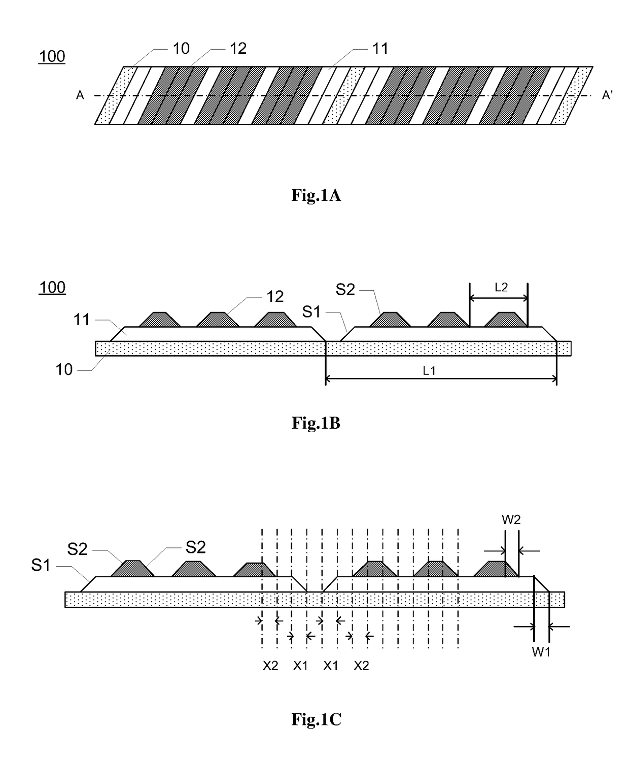
[0033]FIG. 1A illustrates a schematic top view of a touch assembly according to an e...


PUM

PropertyMeasurementUnit
widthaaaaaaaaaa
widthaaaaaaaaaa
thicknessaaaaaaaaaa

Abstract

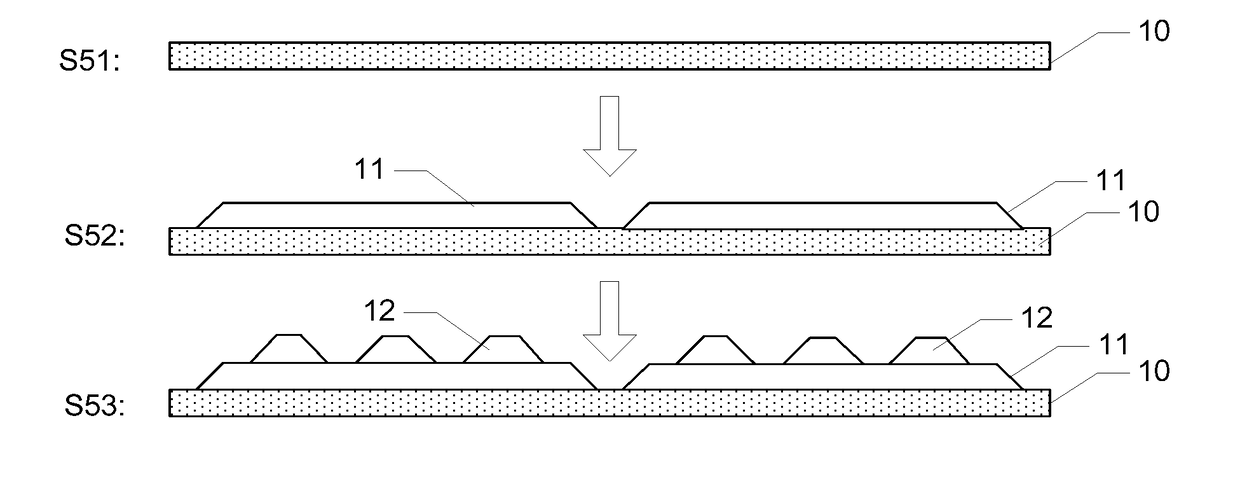
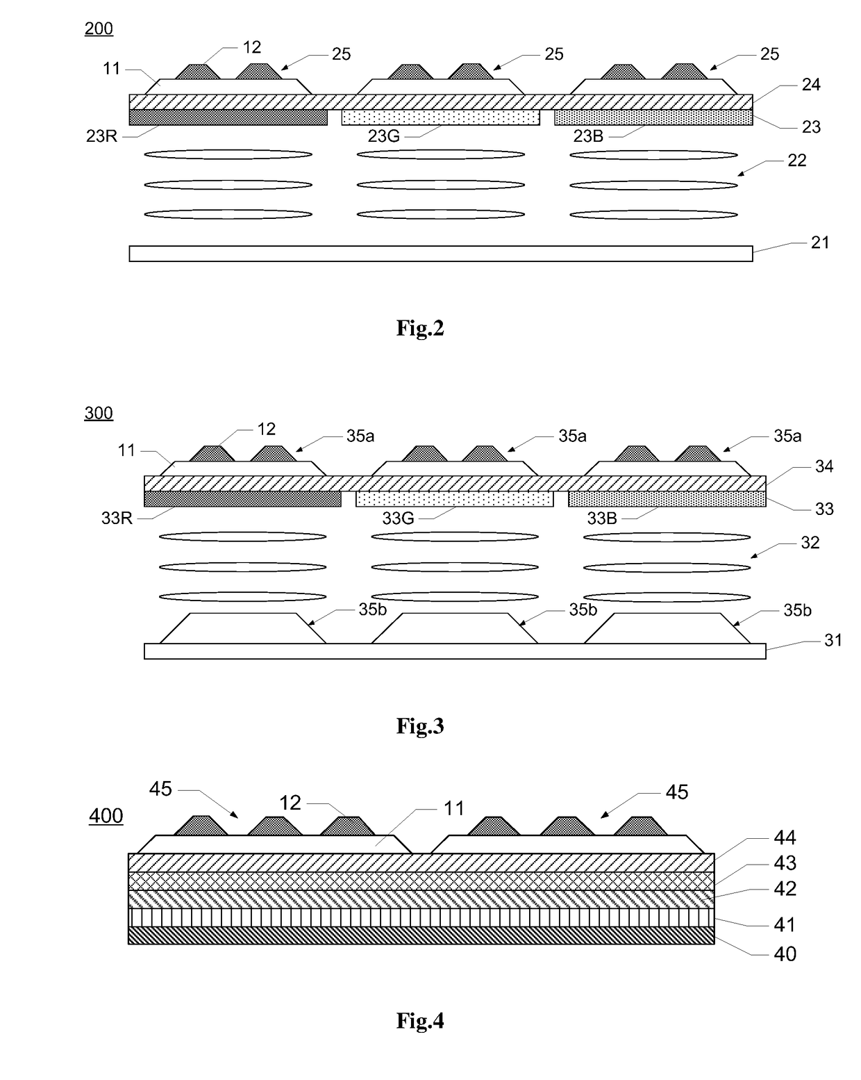
A touch assembly, a display panel containing the touch assembly, and method for manufacturing the touch assembly are provided in embodiments of the disclosure. The touch assembly includes: a substrate; and a plurality of touch electrodes. Each of the plurality of touch electrodes includes a first touch electrode portion and a plurality of second touch electrode portions provided on the first touch electrode portion, and the first touch electrode portions of all of the plurality of touch electrodes are provided alternately in a first period on the substrate and distributed to space apart from one another, and the second touch electrode portions are provided alternately in a second period on each of the first touch electrode portions and distributed to space apart from one another, the second period being smaller than the first period.

Description

[0001]The present disclosure claims the benefit of Chinese Patent Application Invention No. 201611005528.3 filed on Nov. 11, 2016 in the State Intellectual Property Office of China, the whole disclosure of which is incorporated herein by reference.BACKGROUND OF THE DISCLOSUREField of the Disclosure[0002]Embodiments of the present disclosure relate to the technical field of display, and in particular, to a touch assembly, a display panel and a method for manufacturing a touch panel.Description of the Related Art[0003]In the technical field of display, a touch display panel having touch function gets an increasingly extensive use due to convenience thereof in operation. Typically, specific structures of the touch display panel comprise three types: an Out-Cell Touch Panel having a touch screen which is provided independently of a display panel; an In-Cell Touch Panel having a touch assembly which is provided within a display panel; and an On-Cell Touch Panel having a touch assembly wh...

Claims


Application Information

Patent Timeline
Patent Type & Authority Applications(United States)
IPC IPC(8): G06F3/041G02F1/1333G02F1/1335H01L27/32
CPCG06F3/0412G02F1/13338G02F1/133514H01L27/323G02F2201/123G06F3/042G06F2203/04103H10K59/40G06F3/041
Inventor GUO, YUANHUILEE, YUNBOK
Owner BOE TECH GRP CO LTD
Learn More