
Microfluidic device

a microfluidic device and liquid phase technology, applied in the field of liquid phase separation, can solve the problems of specimen loss, valves and connectors, and parts of specimens that remain in dead volumes, and achieve the effect of preventing specimen loss, preventing specimen loss, and preventing specimen loss

Active Publication Date: 2018-07-19
PHARMAFLUIDICS NV
View PDF12 Cites 0 Cited by
  • Summary
  • Abstract
  • Description
  • Claims
  • Application Information

AI Technical Summary

Benefits of technology

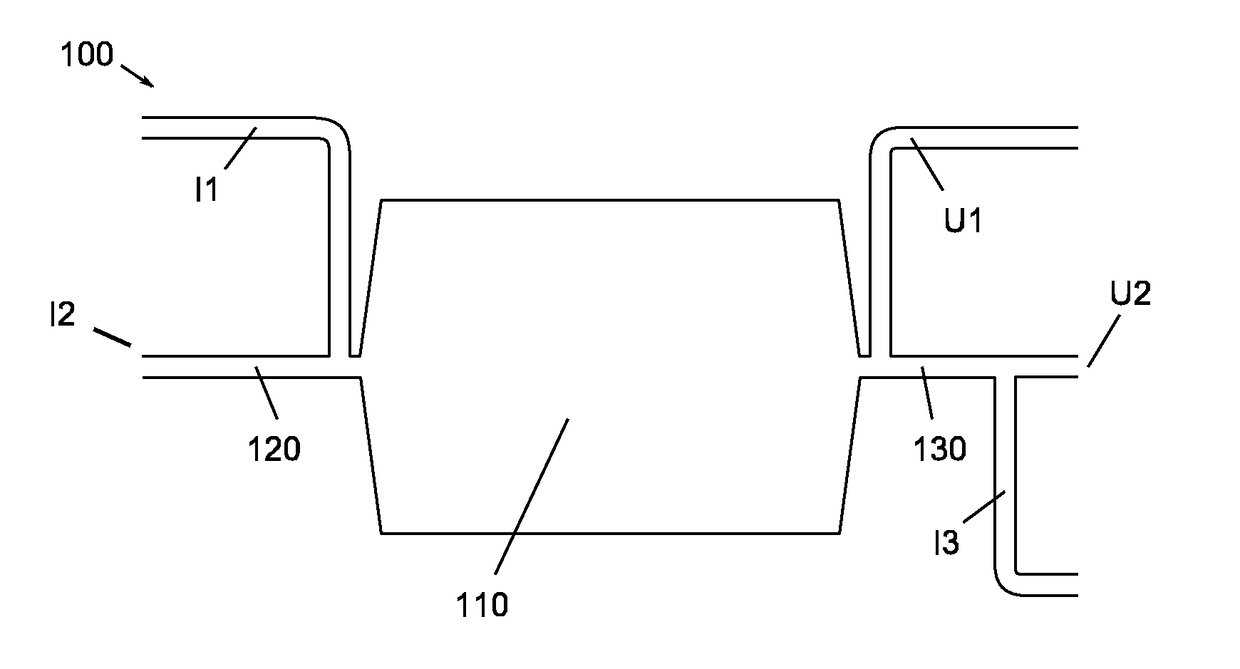
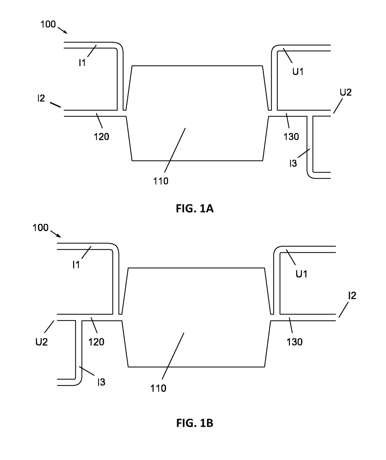
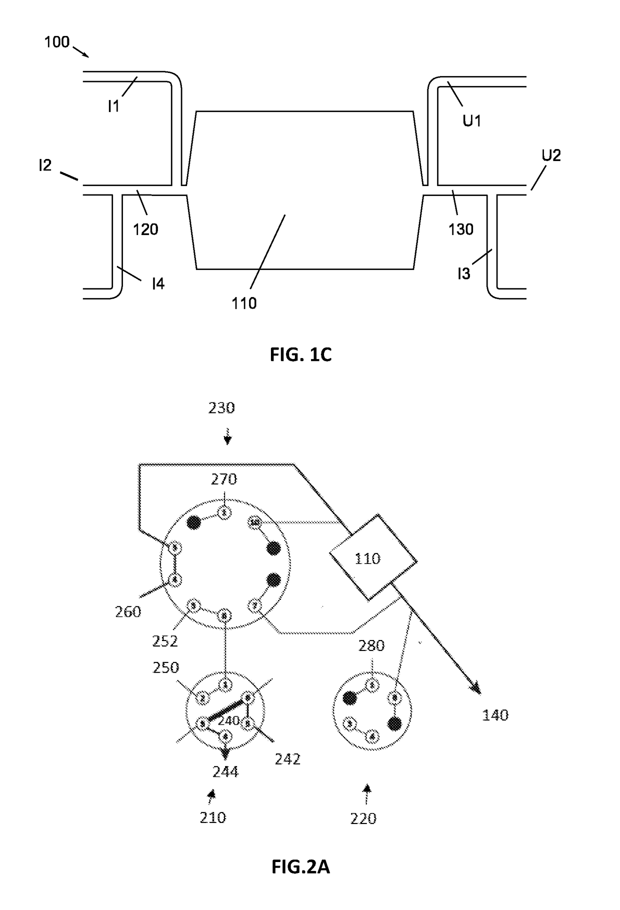
The present invention relates to a microfluidic device for separating phases of interest in a sample. The device has several technical advantages. Firstly, the phase no longer needs to pass through a valve, avoiding blockage and dead volumes. Secondly, the device allows bidirectional flow directions, ensuring efficient separation and elution. Thirdly, the device prevents leakage of the sample during loading and separating. Overall, the microfluidic device improves the efficiency and accuracy of the separation process.

Problems solved by technology

However, due to their position in the specific configuration of devices in the state of the art, these valves and connectors often also have the disadvantage that a part of the specimen stays behind in dead volumes of or introduced by the valves.
This may not only have a negative effect on the amount of specimen available but may also lead to contamination of the various separated phases, causing separation to happen less efficiently.
In addition, in the traditional arrangement, these dead volumes introduce a significant plug broadening during the injection step causing the analytical separation to be negatively affected.

Method used


Image

  • Microfluidic device
  • Microfluidic device
  • Microfluidic device

Examples


Embodiment Construction

[0046]The present invention will be described in respect of specific embodiments and with reference to certain drawings, however the invention will not be restricted thereto but will only be limited by the claims.

[0047]Reference throughout this specification to “one embodiment” or “an embodiment” means that a specific feature, structure or characteristic described in connection with the embodiment has been included in at least one embodiment of the present invention. So, occurrence of the expressions “in one embodiment” or “in an embodiment” in various locations throughout this specification do not necessarily all need to refer to the same embodiment all the time, but may do so. Furthermore, the specific features, structures or characteristics may be combined in any suitable manner as would be clear to a person skilled in the art on the basis of this publication, in one or several embodiments.

[0048]Similarly, it should be appreciated that in the description of sample embodiments of ...


PUM


Abstract

A microfluidic device for separating a phase in a specimen has been described. This is based on a microfluidic trapping area, channels connected to it and integrated inputs and outputs connected onto the channels. An additional integrated input is provided which allows the flow in the device to be controlled and which may prevent leaking of the specimen and the phase.

Description

FIELD OF THE INVENTION[0001]The present invention relates to the field of separating liquid phases. More particularly, the present invention relates to microfluidic systems having a particular configuration for separating liquid phases, to be used for example for chromatography.BACKGROUND OF THE INVENTION[0002]Chemical reactor systems that make use of liquid propagation have a large number of applications, including production of chemical components, synthesis of nano-particles, separation and / or extraction of components, etc.[0003]In separation techniques based on liquid propagation, use is typically made of the difference in affinity of various substances with a mobile phase and a stationary phase and / or of the difference in partition coefficients for partitioning of components. As each substance has its own “bonding power” to the stationary phase, they will be moved along faster or slower with the mobile phase and as such, certain substances can be separated from others. In princ...

Claims


Application Information

Patent Timeline
IPC IPC(8): G01N30/06G01N30/60
CPCG01N30/06G01N30/6095G01N2030/027G01N2030/385G01N1/405G01N30/08G01N30/6004G01N2030/085G01N2030/383
Inventor OP DE BEECK, JEFFJACOBS, PAULDE MALSCHE, WIM
Owner PHARMAFLUIDICS NV
Learn More