Eureka AIR delivers breakthrough ideas for toughest innovation challenges, trusted by R&D personnel around the world.

Plastic cap applicator

Active Publication Date: 2018-07-19
COLORIGHT
View PDF10 Cites 4 Cited by
  • Summary
  • Abstract
  • Description
  • Claims
  • Application Information

AI Technical Summary

Benefits of technology

The patent describes a support device for a dispensing container that includes a tilt valve stem for dispensing a cosmetic cream. The support device consists of a cap made of plastic material that has an opening for receiving the tilt valve stem and an outer surface that attaches to the dispensing container via threads. A valve is positioned between the inner surface of the cap and the tilt valve stem and is made of rubber. The cosmetic cream is provided within the dispensing container at zero pressure. The patent also mentions that the valve can be placed in a recess on the inner surface of the cap. The technical effect of this invention is to provide a support device for a dispensing container that enables efficient and easy dispensing of cosmetic cream without experiencing a return force backlash and to provide a valve that reinforces the return force experience by the stem.

Problems solved by technology

Regular aerosol tilt-valves present two main inadequacies when applied to the requirements of cosmetic cream dispensing system:The creams contain peroxides that cannot come into contact with metal.The creams are shipped under low or even zero bars pressure above atmosphere, significantly lower than most use cases, leading to leakage of material.
This results in valves that do not return fully to the upright position when tilted, leading to material leakage.

Method used


Image

  • Plastic cap applicator
  • Plastic cap applicator
  • Plastic cap applicator

Examples


Embodiment Construction

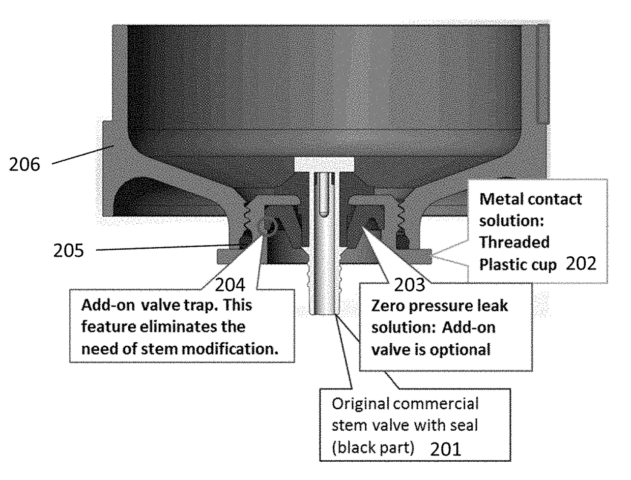
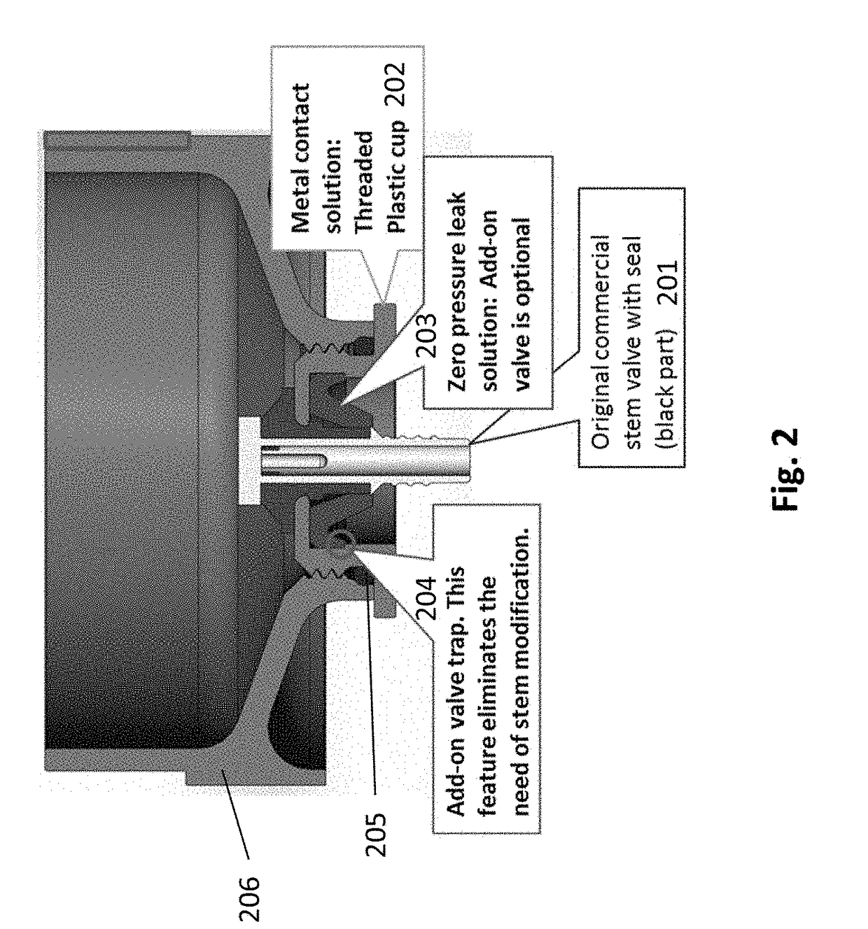
[0019]FIG. 2 shows a tilt valve structure according to an embodiment. The structure includes a conventional stem valve with seal 201. The stem valve fits through an opening in a threaded plastic cup 202. An add on valve 203 is embedded within the plastic cup 202. Specifically, the plastic cup 202 includes an add on valve trap 204, which is a recess that supports an outer portion of the add on valve.

[0020]A crimped metal cup as used in the conventional art cannot be used with certain cosmetic creams due to its reactivity with peroxide in the cream. The present embodiment solution provides a plastic cup fully compatible with current valves. The plastic cup can be made of any number of plastic materials known in the art, such as the same material as used for a plastic container. As shown in FIG. 2, this plastic cup attaches directly onto the container 206 and sealed using an O-ring 205.

[0021]The add-on valve 203 reinforces the return force experience by the stem allowing it to seal its...


PUM


Abstract

A support device configured to be coupled to a dispensing container that includes a tilt valve stem for dispensing a cosmetic cream. The support device includes a cap made of a plastic material that includes an opening for receiving the tilt valve stem and an outer surface configured to attach to the dispensing container, wherein the outer surface attaches to the dispensing container via threads; and a valve configured to be disposed between an inner surface of the cap and the tilt valve stem, the valve being configured to reinforce a return force experience by the stem.

Description

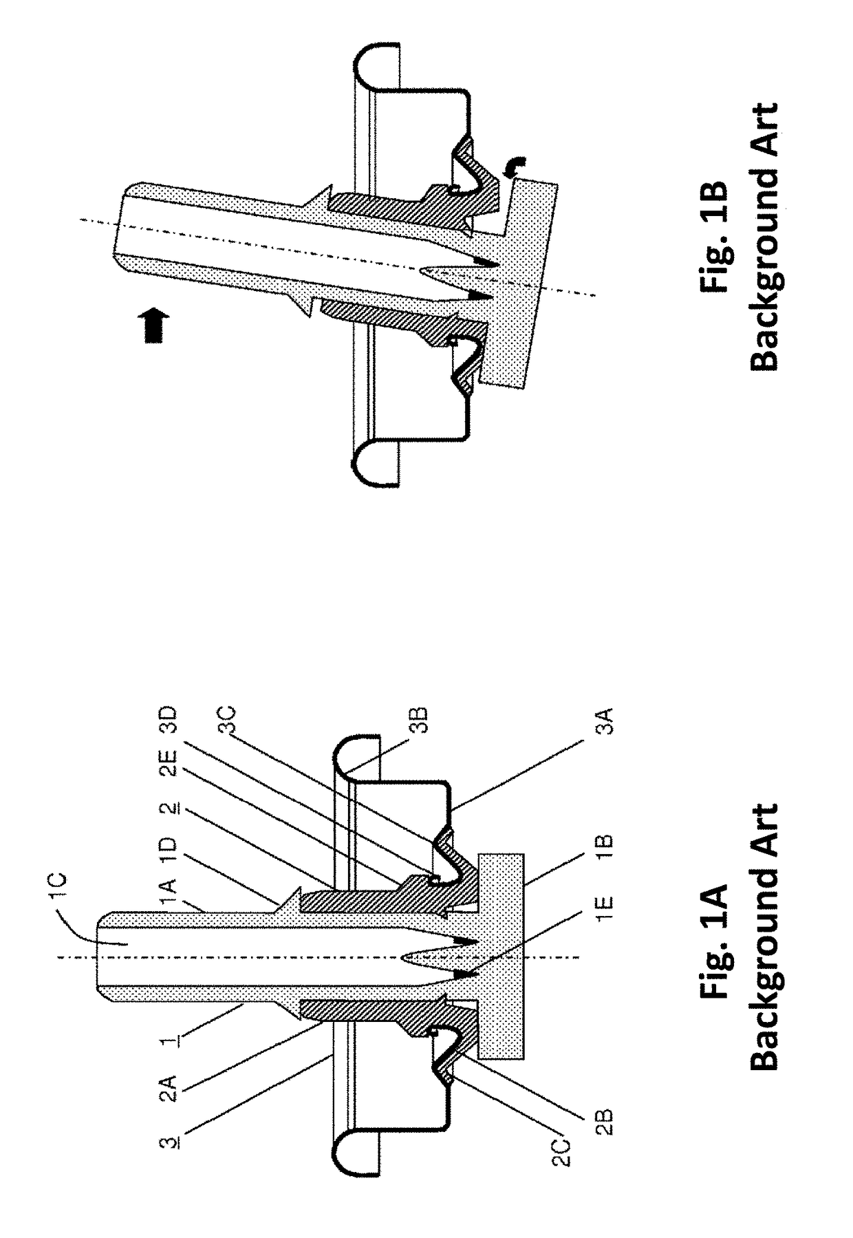
CROSS-REFERENCE TO RELATED APPLICATIONS[0001]This application claims the benefit of U.S. provisional application Ser. No. 62 / 447,230, filed on Jan. 17, 2017. The entire contents of which are incorporated herein by reference.BACKGROUND1. Field of the Invention[0002]The present invention relates to a tilt valve used in a container for dispensing a cosmetic formulation.2. Description of the Related Art[0003]Conventional tilt valves consist of a hollow tubular stem attached to an elastic sealing grommet. The grommet is attached to a metal cup that is snapped onto the container. When tilting the valve, material is pushed by the positive pressure in the container through orifices in the stem. A combination of the elasticity of the grommet and the pressure of inside the container seals the valve back into the upright position when the user stops tilting the valve.[0004]FIGS. 1A and 1B show a conventional tilt valve as disclosed in EP 2481688 (incorporated herein by reference). The structur...

Claims


Application Information

Patent Timeline
IPC IPC(8): B65D47/24B65D41/04
CPCB65D47/248B65D41/0407B65D83/46
Inventor DOUVDEVANI, SHMUELNAFTALY, ZAHMIKLATZKY, EFRAIMMANDELIK, DANIEL
Owner COLORIGHT
Why Eureka
Eureka Blog
Learn More