Turbidity sensor based on ultrasound measurements

a technology of turbidity sensor and ultrasound, which is applied in the field of turbidity sensors, can solve the problems of not being able to function as a permanent part, not being able to accurately detect the response signal, and not being able to accurately measure the turbidity, so as to achieve simple and low cost, still robust and reliable measurement

Active Publication Date: 2018-07-05
KAMSTRUP
View PDF9 Cites 3 Cited by
  • Summary
  • Abstract
  • Description
  • Claims
  • Application Information

AI Technical Summary

Benefits of technology

[0005]It would be advantageous to provide a simple and low cost turbidity measurement device which is still robust and reliable for measuring turbidity of the fluid in a utility network, hereby allowing utility companies to distribute such devices at several positions in the utility network.

Problems solved by technology

Optical turbidity equipment, however, is not well-suited for functioning as a permanently mounted part of a utility network due to the forming of coatings of minerals and / or biofilms on the optical surfaces, which will disturb the turbidity measurements and necessitate frequent maintenance.
Furthermore, such optical turbidity measurement equipment is expensive and can thus in practice only be installed at a limited number of positions in a utility network.

Method used


Image

  • Turbidity sensor based on ultrasound measurements
  • Turbidity sensor based on ultrasound measurements
  • Turbidity sensor based on ultrasound measurements

Examples


Embodiment Construction

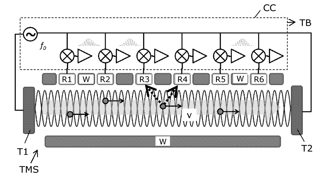
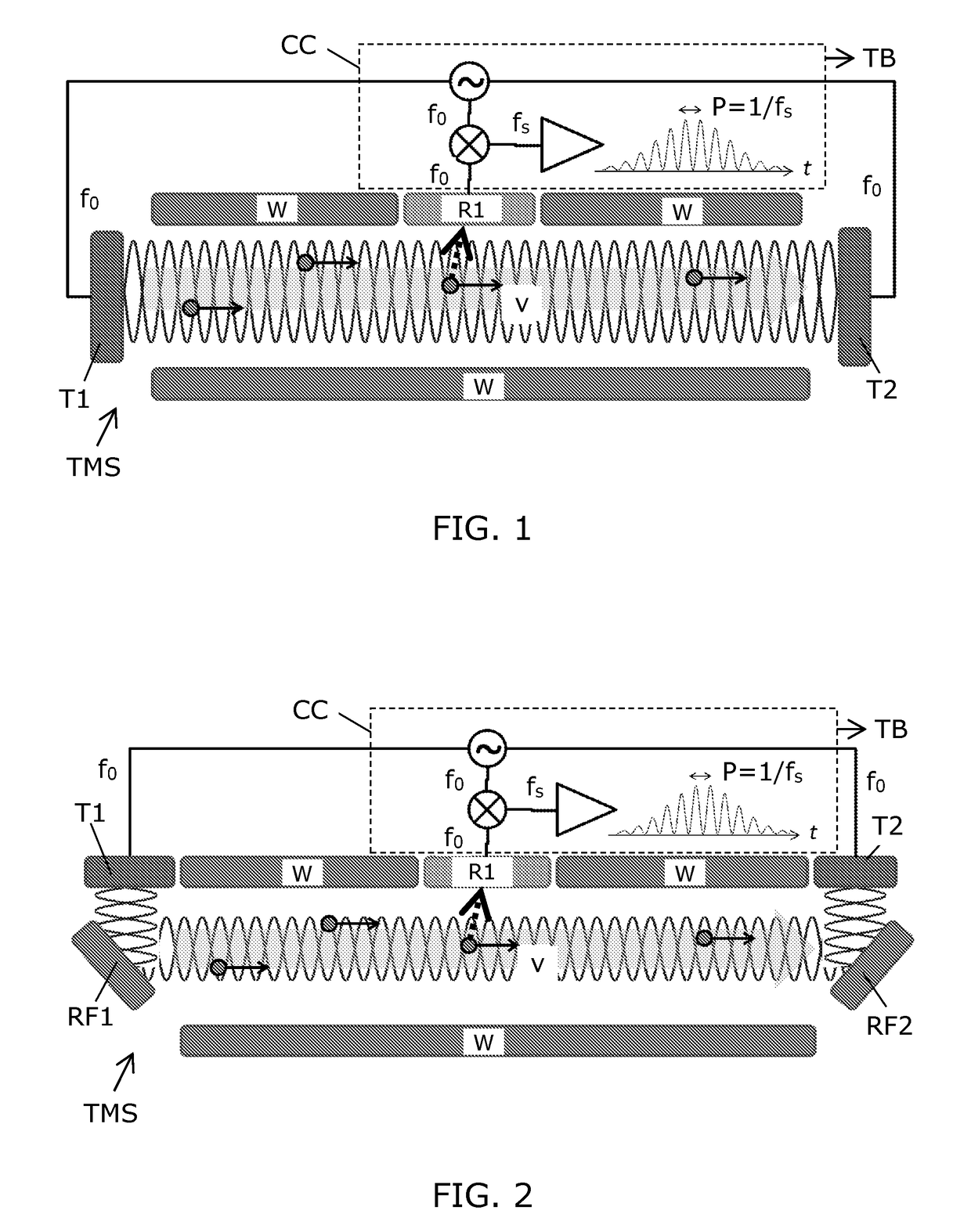
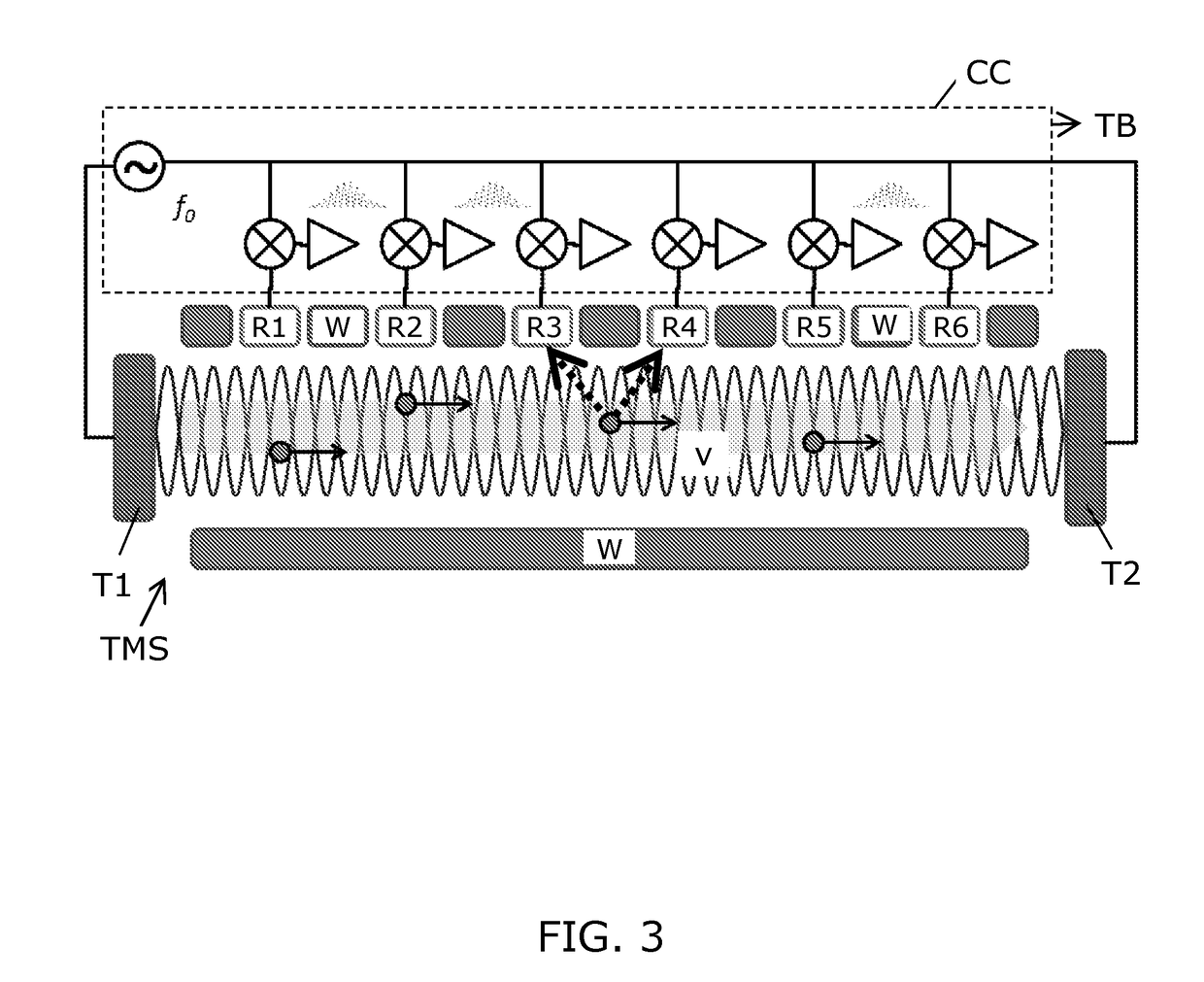
[0083]FIG. 1 illustrates a sketch of a turbidity measurement device embodiment with a flow tube with walls W, where two transducers T1, T2 are arranged in the flow tube and serve as end sections for the turbidity measurement section TMS between which two ultrasonic standing waves are generated. The dark circles indicate particles flowing along the fluid in the flow tube with flow rate v. A receiver transducer R1 is arranged at the wall W of the flow tube at a central position between the two transducers T1, T2. For one particle an ultrasonic response to the ultrasonic standing wave is indicated with a dashed arrow towards the receiver transducer R1 which then captures the ultrasonic response from the particle. With an ultrasonic standing wave with frequency f0, the expected frequency fs of high intensity scattering of a particle in a fluid with flow rate v is: fs=(v / c)f0, where c is the speed of the ultrasonic wave in the fluid. Thus, a high intensity response from particle scatteri...


PUM

PropertyMeasurementUnit
sizeaaaaaaaaaa
distanceaaaaaaaaaa
frequencyaaaaaaaaaa

Abstract

A turbidity measurement device for measuring turbidity of a fluid flowing in a flow tube. A first transducer transmits ultrasonic signals through the fluid in the turbidity measurement section so as to provide a first ultrasonic standing wave between the first and second section ends. A receiver transducer receives the ultrasonic scattered response from particles in the fluid flowing through the turbidity measurement section. A control circuit operates the transducers and generates a signal indicative of the turbidity of the fluid in response to signals received from the receiver transducer. Preferably, the device may comprise a second transducer for generating a second ultrasonic standing wave with the same frequency, and further the two transducers may be used to generate a measure of flow rate by means of known ultrasonic techniques. This flow rate may be used in the calculation of a measure of turbidity. Both turbidity facilities and flow rate facilities may be integrated in a consumption meter, such as a heat meter or a water meter.

Description

FIELD OF THE INVENTION[0001]The present invention relates to the field of turbidity sensors for measurement of turbidity of a fluid. Especially, the invention provides a device capable of measuring turbidity based on ultrasonic measurements. Further, the invention provides an ultrasonic consumption meter, or utility meter, comprising such turbidity sensor.BACKGROUND OF THE INVENTION[0002]Worldwide the consumption of clean water for drinking is increasing. Drinking water is retrieved from underground wells, but also surface water or even de-salted sea water are used as drinking water. Thus, there is a demand for utility companies to measure cleanness of the water supplied to the utility network.[0003]A complete analysis of cleanness of water involves complicated biochemical analyses, however in some cases a measure of water quality obtained by means of a turbidity measurement can be sufficient, i.e. measurement of the amount of particles in the fluid as a measure of cleanness of the ...

Claims


Application Information

Patent Timeline
Patent Type & Authority Applications(United States)
IPC IPC(8): G01N29/032
CPCG01N29/032G01N2291/015G01N2291/02416G01D4/00G01D4/002G01D4/004G01M3/243G01F1/666G01N2291/02408G01M3/2815G01N2291/02836G01N2291/02872G01N2291/102G01N29/222G01N29/50Y02B90/20Y04S20/30G01N2291/044
Inventor NIELSEN, SOREN TONNESLAURSEN, PETER SCHMIDTSORENSEN, JENS LYKKEDUPONT, SUNE HOVEROUST
Owner KAMSTRUP
Why Eureka
Try Eureka