
Systems and methods for early well kick detection

a well kick detection and system technology, applied in the field of oil and gas drilling operations, can solve the problems of further complicated, well kick, costly environmental and financial consequences,

Inactive Publication Date: 2018-07-05
HYDRIL USA DISTRIBUTION LLC
View PDF4 Cites 45 Cited by
  • Summary
  • Abstract
  • Description
  • Claims
  • Application Information

AI Technical Summary

Benefits of technology

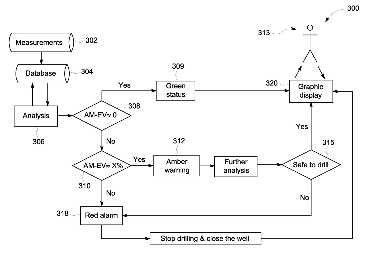
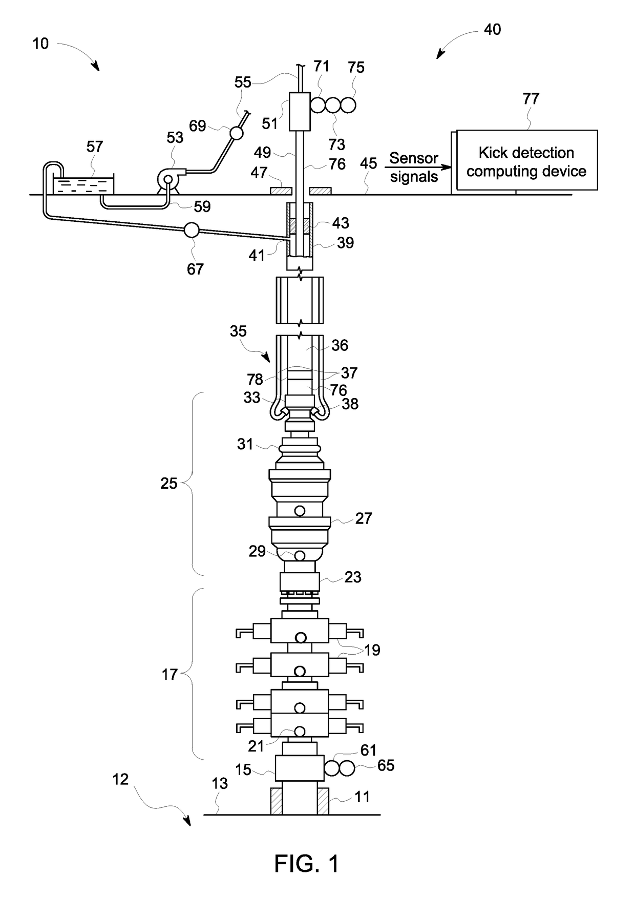
The patent text describes a system and method for detecting kicks in a drilling system of a well. The system includes sensors and a kick detection computing device that receives data from the sensors and generates estimated values for various kick indicators during normal drilling conditions and a kick condition. The computing device then generates a signal based on the deviation between the estimated values and the data measurements, which activates a green, amber, or red alarm to alert the operator of the drilling system. The operator computing device displays the kick detection status of the drilling system. The technical effect of the system and method is to enable early detection and timely response to kicks, ensuring safe and efficient drilling operations.

Problems solved by technology

An undesirable event in a drilling operation is taking an influx of formation fluids into a wellbore, known as a well kick.
This is further complicated when drilling in deep water or ultra-deep water because of the pressure on the sea floor by the water above it.
On some known occasions, the pressure in the hole forces material back into the wellbore and cause a well kick.
An uncontrolled well kick may eventually result in a blowout, leading to costly environmental and financial consequences.
However, the definition of thresholds is usually based on the operator's experience, thus not being a reliable method for well kick detection.

Method used


Image

  • Systems and methods for early well kick detection
  • Systems and methods for early well kick detection
  • Systems and methods for early well kick detection

Examples


Embodiment Construction

[0013]In the following specification and the claims, reference will be made to a number of terms, which shall be defined to have the following meanings.

[0014]The singular forms “a”, “an”, and “the” include plural references unless the context clearly dictates otherwise.

[0015]“Optional” or “optionally” means that the subsequently described event or circumstance may or may not occur, and that the description includes instances where the event occurs and instances where it does not.

[0016]Approximating language, as used herein throughout the specification and claims, may be applied to modify any quantitative representation that could permissibly vary without resulting in a change in the basic function to which it is related. Accordingly, a value modified by a term or terms, such as “about,”“substantially,” and “approximately,” are not to be limited to the precise value specified. In at least some instances, the approximating language may correspond to the precision of an instrument for ...


PUM


Abstract

An early kick detection system including a kick detection computing device coupled to at least one sensor associated with a drilling system of a well. The kick detection computing device is configured to receive measurement data from the at least one sensor. The measurement data includes one or more kick indicators used to identify a well kick. The kick detection computing device generate an estimated value for each of the one or more kick indicators during simulated normal drilling conditions and simulated kick conditions. The kick detection computing device determines a deviation value and generates a signal based on the deviation value. The signal activates a green status, an amber warning, or a red alarm to indicate a kick detection status of the drilling system.

Description

BACKGROUND[0001]The field of the disclosure relates generally to oil and gas drilling operations and, more particularly to a system and method for detecting a well kick during drilling operations using a drilling hydraulic model.[0002]An undesirable event in a drilling operation is taking an influx of formation fluids into a wellbore, known as a well kick. It is known that there is a preexistent pressure on the formations of the earth, which, in general, increases as a function of depth due to the weight of the overburden on particular strata. This weight increases with depth so the prevailing or quiescent bottom hole pressure is increased in a generally linear curve with respect to depth. As the well depth is doubled in a normal-pressured formation, the pressure is likewise doubled. This is further complicated when drilling in deep water or ultra-deep water because of the pressure on the sea floor by the water above it. Thus, high pressure conditions exist at the beginning of the h...

Claims


Application Information

Patent Timeline
IPC IPC(8): E21B21/08E21B47/10E21B44/00E21B47/06G08B5/36G08B21/18G06F17/50E02B1/02
CPCE21B21/08E21B47/1005E21B44/00E21B47/06E02B1/02G08B5/36G08B21/182G06F17/5009E21B47/065E21B2200/22
Inventor SANCHEZ SOTO, GERARDO ALONSONEMOTO, RAFAEL HORSCHUTZ
Owner HYDRIL USA DISTRIBUTION LLC
Learn More