Liquid ejecting apparatus, and cleaning method of transport belt of liquid ejecting apparatus

Active Publication Date: 2018-07-05
SEIKO EPSON CORP
View PDF1 Cites 8 Cited by
  • Summary
  • Abstract
  • Description
  • Claims
  • Application Information

AI Technical Summary

Benefits of technology

The patent describes a liquid ejecting apparatus that improves cleaning performance while suppressing vibration and increasing rigidity of the cleaning device without increasing cost. The apparatus uses a positioning pin and a groove portion to hold the cleaning unit in place, preventing separation during cleaning. A locking mechanism is also used to reduce power consumption. Overall, the patent provides a cost-effective solution for improving cleaning performance of a liquid ejecting apparatus.

Problems solved by technology

There is a problem in that a cost of a liquid ejecting apparatus increases when rigidity of the cleaning device is improved.
In the related art, it was necessary to strengthen rigidity of the apparatus in order to suppress the vibration which occurs in the cleaning unit in order to improve a cleaning performance with respect to the transport belt, and this caused a rise in cost of the liquid ejecting apparatus.
In the related art, it was necessary to strengthen rigidity of the apparatus in order to suppress a vibration which occurs along with an improvement of a cleaning performance with respect to the transport belt, and this caused a rise in cost of the apparatus.

Method used


Image

  • Liquid ejecting apparatus, and cleaning method of transport belt of liquid ejecting apparatus
  • Liquid ejecting apparatus, and cleaning method of transport belt of liquid ejecting apparatus
  • Liquid ejecting apparatus, and cleaning method of transport belt of liquid ejecting apparatus

Examples


embodiment

[0022]Schematic Configuration of Liquid Ejecting Apparatus

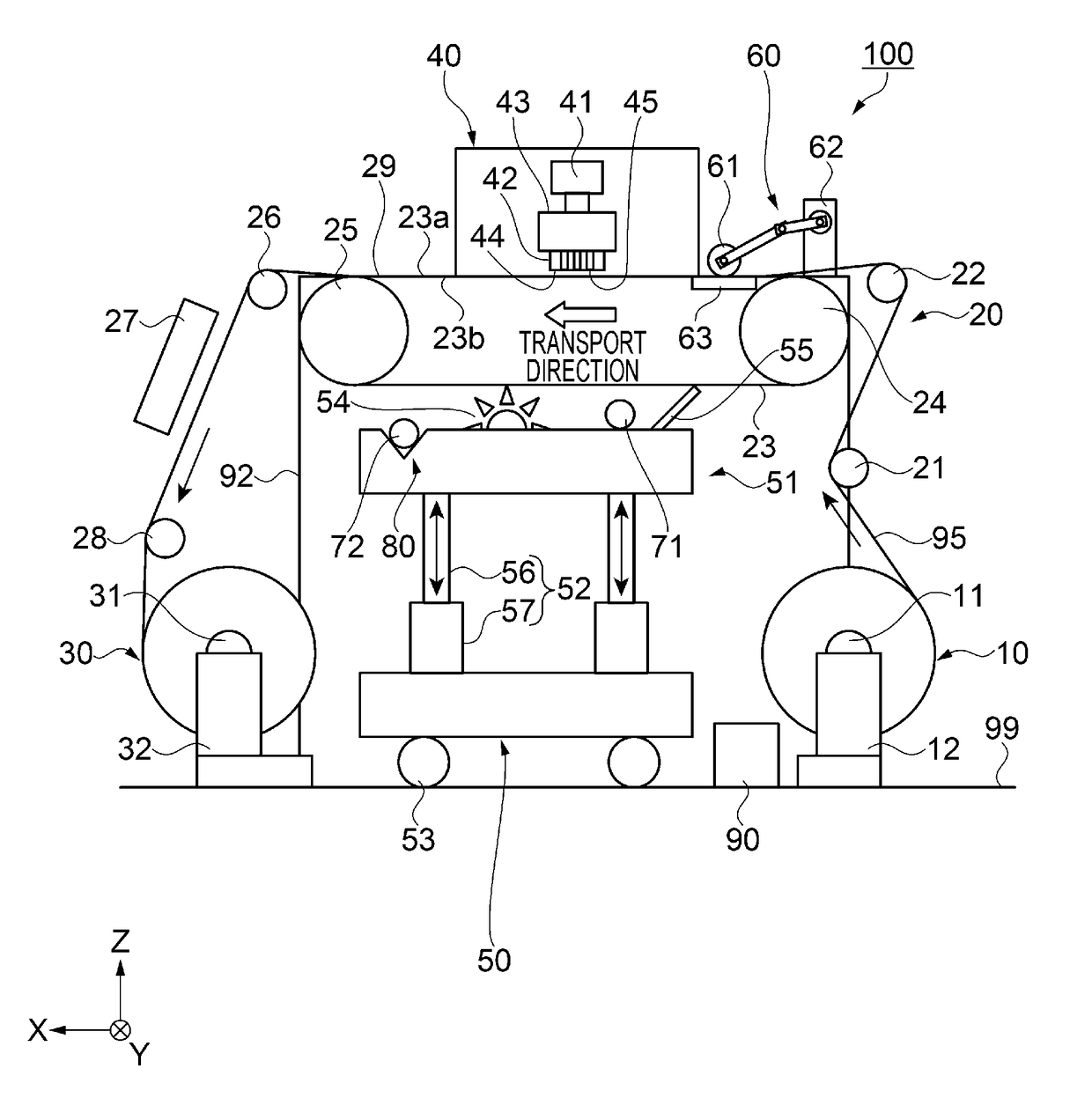
[0023]FIG. 1 is a schematic view which schematically illustrates the entire configuration of a liquid ejecting apparatus according to an embodiment. A liquid ejecting apparatus 100 performs textile printing of a recording medium 95 by forming an image on the recording medium 95. As the recording medium 95, for example, cloth such as cotton, wool, a synthetic fiber, or a mixed fabric is used. According to the embodiment, a configuration in which an image is formed on a belt-shaped recording medium 95 using a roll system will be described as an example; however, it is not limited to this. For example, it may be a system in which a sheet type, or the like, is used.

[0024]As illustrated in FIG. 1, the liquid ejecting apparatus 100 is provided with a recording medium supply unit 10, a recording medium transport unit 20, a recording medium collecting unit 30, a printing unit 40, a cleaning device 50, a medium adhering unit 60, and t...

modification example

[0062]FIG. 5 is a schematic view which illustrates a schematic configuration of a cleaning unit of a liquid ejecting apparatus according to a modification example. FIG. 6 is a sectional view which is taken along line VI-VI in FIG. 5. The liquid ejecting apparatus according to the modification example will be described with reference to FIGS. 5 and 6. In addition, the same constituent portions as those in the embodiment will be given the same reference numerals, and redundant descriptions will be omitted. The liquid ejecting apparatus according to the modification example is provided with a locking mechanism which fixes a cleaning unit to a cleaning position.

[0063]As illustrated in FIG. 5, groove portions 80a and 80b which are engaged with positioning pins 71 and 72 are provided in a cleaning unit 151. Since configurations of the groove portions 80a and 80b are the same as that in the above described groove portion 80, descriptions thereof will be omitted. The cleaning unit 151 is pr...


PUM


Abstract

A liquid ejecting apparatus in which a cleaning performance with respect to a transport belt is improved while suppressing a rise in cost of the apparatus is provided. A liquid ejecting apparatus is provided with a transport belt which transports a recording medium, and a cleaning unit which cleans the transport belt. The cleaning unit can move between a cleaning position and an evacuation position, and is positioned at the cleaning position using positioning pins which are provided in a frame unit as a housing, and a groove portion which is provided in the cleaning unit.

Description

CROSS REFERENCE TO RELATED APPLICATIONS[0001]This application claims priority to Japanese Patent Application No. 2015-124487, filed Jun. 22, 2015. The entire disclosure of Japanese Patent Application No. 2015-124487 is hereby incorporated herein by reference.TECHNICAL FIELD[0002]The present invention relates to a liquid ejecting apparatus, and a cleaning method of a transport belt of the liquid ejecting apparatus.BACKGROUND ART[0003]In recent years, in textile printing with respect to cloth such as cotton, silk, wool, a synthetic fiber, or a mixed fabric, a liquid ejecting apparatus which ejects ink toward the surface of cloth, and performs printing of a pattern, or the like, on the cloth has been used. The liquid ejecting apparatus which is used in textile printing is provided with a transport mechanism which transports a recording medium by mounting the recording medium on an endless transport belt, which is adhesive, so as to treat elastic cloth as a printing medium. In such a li...

Claims


Application Information

Patent Timeline
IPC IPC(8): B08B1/02B41J29/17B08B1/04
CPCB41J11/007B41J13/08B41J29/17B41J2002/16591B41J3/4078B41J2/16538B08B3/022B08B1/20B08B1/32
Inventor JINGUSHI, MASARU
Owner SEIKO EPSON CORP
Why Eureka
Try Eureka