
System and method for preventing collisions between wind turbine blades and flying objects

a technology of wind turbine blades and flying objects, which is applied in the direction of active/predictive/anticipative control, emergency control, and reradiation, etc., can solve the problems of wind turbines causing a hazard to birds and bats, affecting the energy production of birds, and the blade stopping, so as to increase or decrease the rotational speed, increase the safety of birds, and reduce the effect of power consumption

Inactive Publication Date: 2018-06-21
SINTEF ENERGI AS
View PDF6 Cites 10 Cited by
  • Summary
  • Abstract
  • Description
  • Claims
  • Application Information

AI Technical Summary

Benefits of technology

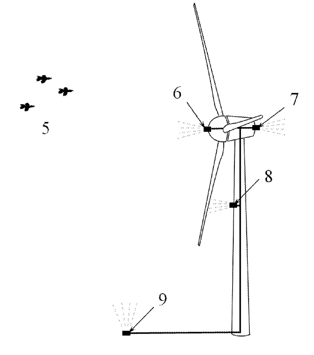
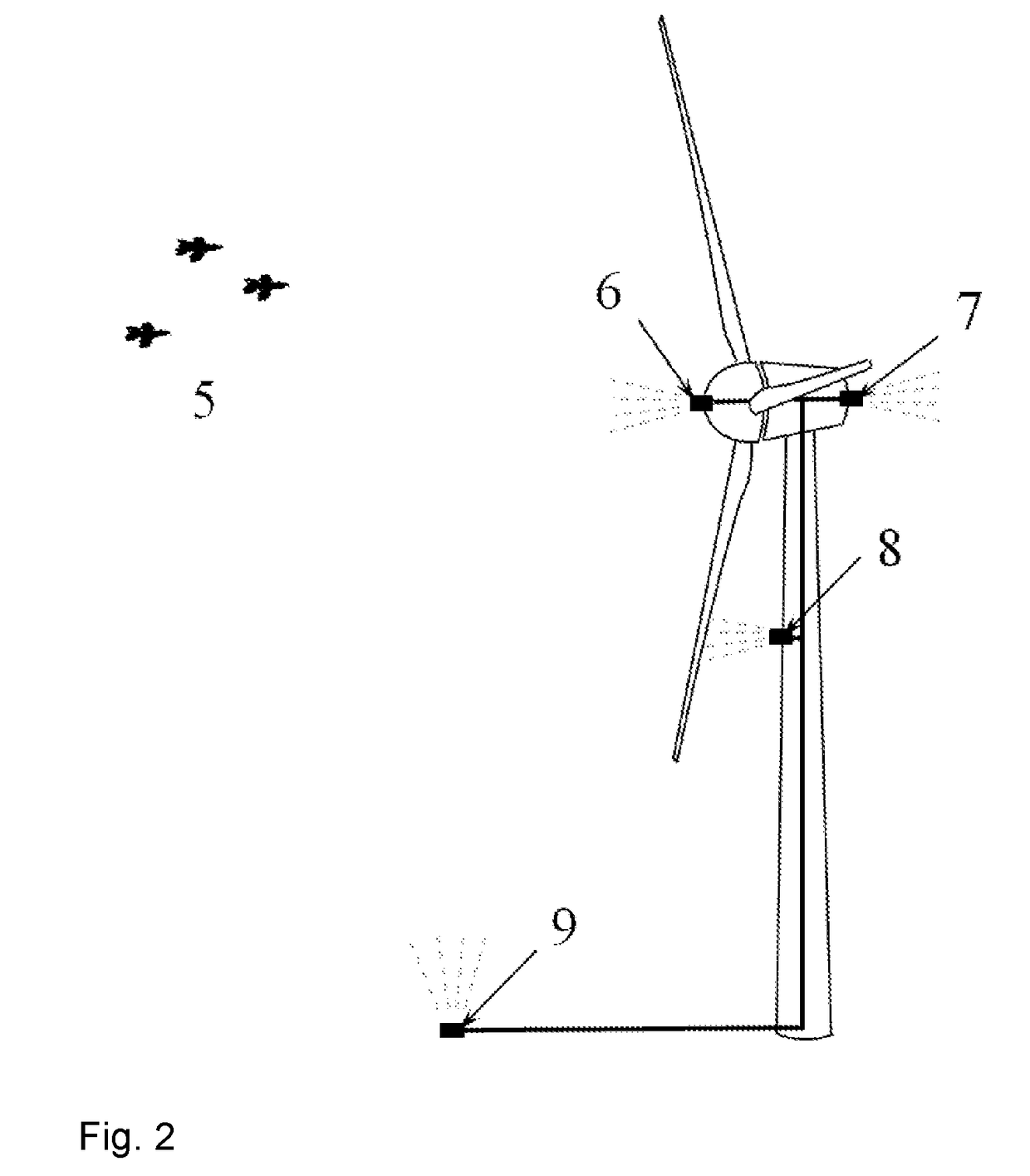
The present invention is about a method, a control module, and a control system for wind turbines to prevent collisions with flying objects such as birds, bats, or drones. The method involves regulating the speed of the wind turbine rotor to avoid collisions with flying objects. The control system measures the position and velocity of the flying objects and adjusts the wind turbine's speed to prevent collisions. This results in increased safety for birds and bats and avoids costly repairs of wind turbine blades. The technical effect is a safer and more environmentally friendly wind energy harvesting system.

Problems solved by technology

Wind turbines represent a hazard to birds and bats.
A bird or bat hit by a wind turbine rotor blade will be killed, and the collision may also damage the rotor blade, which may result in stopping of the turbine and costly repairs of the blade.
A malfunction or other event could cause the aircraft to deviate from the planned flight path.
Employed on a broad scale, such deterrents could have negative ecological impacts, driving away not only birds, but also other non-targeted animals living in the vicinity of wind turbines.
There is also the danger of desensitization, where over repeated exposures the birds become accustomated to the deterrents, thereby negating the effect.
Reduced rotor speed results in curtailment of power production, and thus loss of revenue.

Method used


Image

  • System and method for preventing collisions between wind turbine blades and flying objects
  • System and method for preventing collisions between wind turbine blades and flying objects
  • System and method for preventing collisions between wind turbine blades and flying objects

Examples


Embodiment Construction

[0025]The present invention will be described with reference to the drawings. The same reference numerals are used for the same or similar features in all the drawings and throughout the description.

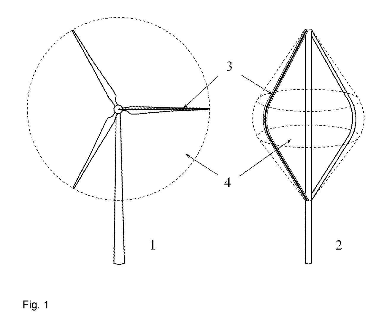
[0026]A horizontal-axis wind turbine 1 and a vertical-axis wind turbine 2 for energy harvesting are illustrated in FIG. 1. In each type of wind turbine, the profile 3 of the blades can be described by a theoretical line or curve (illustrated with dotted lines in FIG. 1). The curve is most likely contained within the airfoil profile at each spanwise location along the blade, but might also be located outside the airfoil profile. This curve, when swept 360 degrees about the axis of rotation, defines a swept surface 4 associated with the rotor blades of the wind turbine. Multiple curves might be defined, resulting in a family of swept surfaces; the present invention applies to any number of swept surfaces, or other similar regions of space associated with the blade trajectory, although for ...


PUM


Abstract

A system and a method for control of a wind turbine for prevention of collisions between the rotor and flying objects such as birds, bats, and remotely-piloted aircraft is disclosed. The position and velocity of one or more flying objects is measured. The probability of the positions of the objects when they pass through the surface swept by the rotor blades is estimated. Increasing or decreasing the speed of the wind turbine rotor is performed such that the probability of collision between the rotor blades and the one or more objects is reduced or minimized, while otherwise continuing power production as usual.

Description

INTRODUCTION[0001]The present invention concerns a method, a collision prevention control module, and a collision prevention control system for preventing collisions between flying objects, such as birds, bats, and remotely-piloted aircraft, and wind turbine blades, without significantly changing the operating state or decreasing the energy production of the wind turbines. The invention also concerns a wind turbine provided with a collision prevention control system.BACKGROUND[0002]Wind turbines represent a hazard to birds and bats. A bird or bat hit by a wind turbine rotor blade will be killed, and the collision may also damage the rotor blade, which may result in stopping of the turbine and costly repairs of the blade. Other scenarios could be envisioned where a collision risk may exist between flying objects and wind turbine blades. For instance, remotely piloted drone aircraft have been proposed for inspection and maintenance of blades, implying that such aircraft will be active...

Claims


Application Information

Patent Timeline
Patent Type & Authority Applications(United States)
IPC IPC(8): F03D7/00G05B13/02G01S13/93G01S13/933
CPCF03D7/00G05B13/026F05B2270/101F05B2270/404F05B2270/107F05B2270/304F05B2220/706F05B2240/912F05B2270/805F05B2270/8042F05B2270/8041F03D80/10Y02E10/728Y02E10/72G01S7/415G01S13/56G01S13/93
Inventor MERZ, KARL OTTOTANDE, JOHN OLAV GI.AE BUTTED.VER
Owner SINTEF ENERGI AS
Learn More