
Insulated container for and method of cooling a heated tooling component

a technology of insulated containers and tooling components, which is applied in the direction of containers preventing decay, forming tools, foundry moulding apparatus, etc., can solve the problems of distortion and cracking of tooling components, affecting the cooling effect of the component, so as to achieve the effect of controlling the air flow rate through the chamber

Inactive Publication Date: 2018-06-21
ROLLS ROYCE PLC
View PDF1 Cites 0 Cited by
  • Summary
  • Abstract
  • Description
  • Claims
  • Application Information

AI Technical Summary

Benefits of technology

The patent describes an insulated container for cooling a heated tooling component used in a superplastic forming process. The container has an inlet port and a vent that allow air to enter and eject the heated tooling component, creating a convective air flow to cool it. The size of the vent can be adjusted to control the air flow rate. The container is formed by a thermally insulated base, side wall, and upper wall, and the heated tooling component is positioned inside it. The insulated container provides a convenient way to cool the tooling component during the process.

Problems solved by technology

However, since the tooling components have non-uniform thickness, after the forming process is complete, the tooling components cool in a non-uniform manner, which leads to the establishment of temperature differentials and thermal stresses within the component.
Such thermal stresses can lead to distortion and cracking of the tooling components, which are expensive and time-consuming to replace.

Method used


Image

  • Insulated container for and method of cooling a heated tooling component
  • Insulated container for and method of cooling a heated tooling component
  • Insulated container for and method of cooling a heated tooling component

Examples


Embodiment Construction

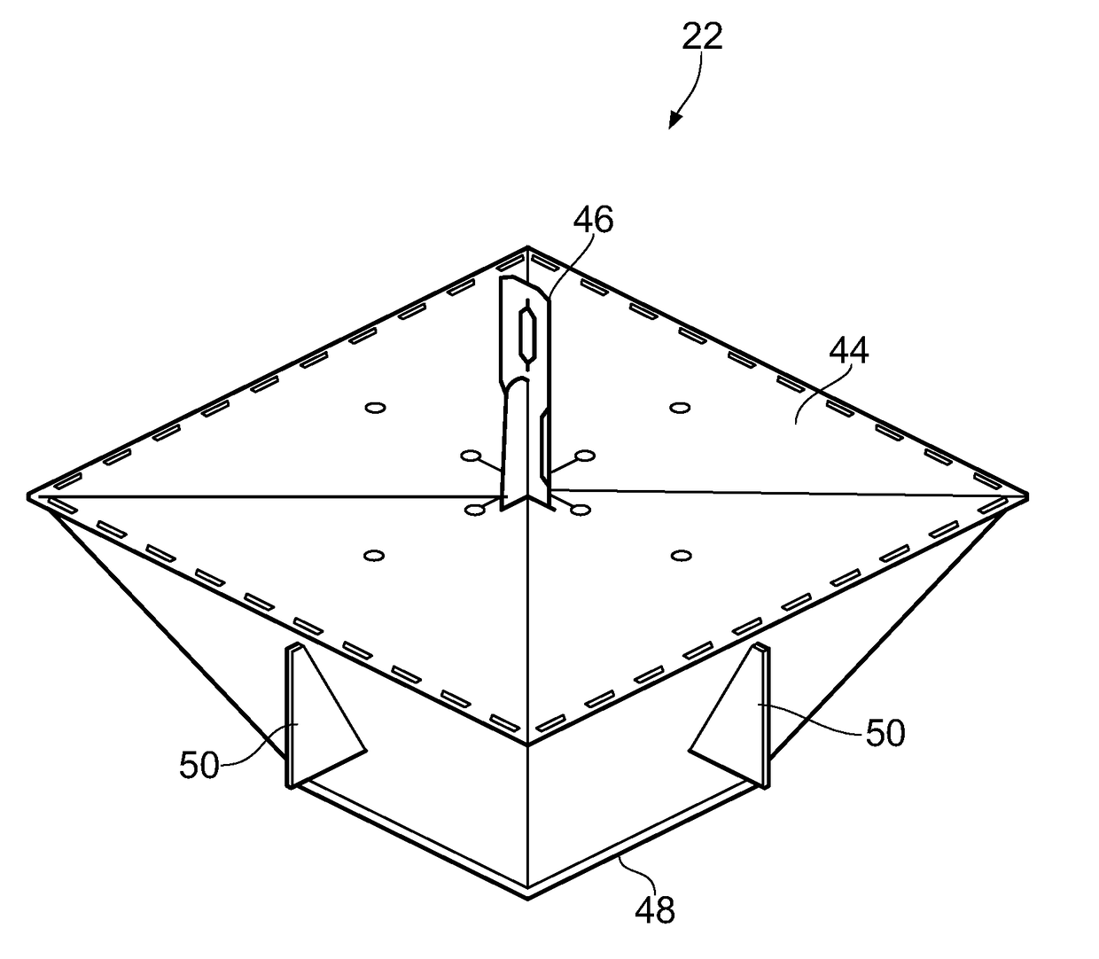
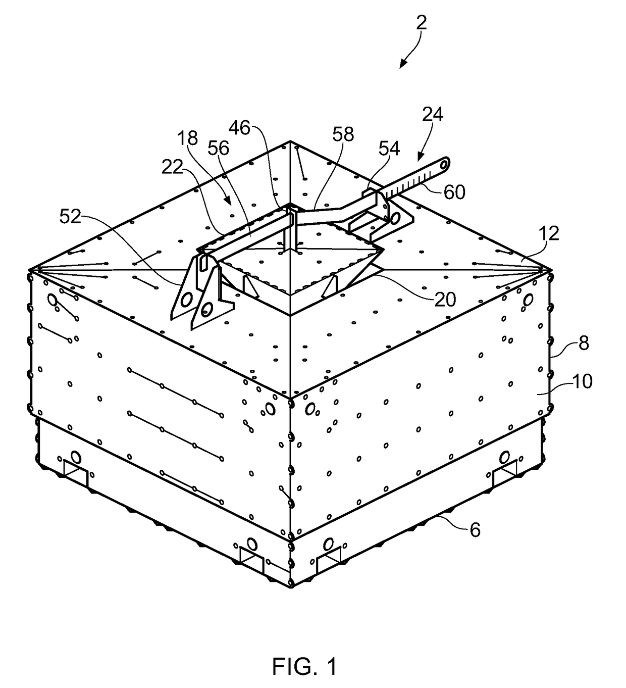
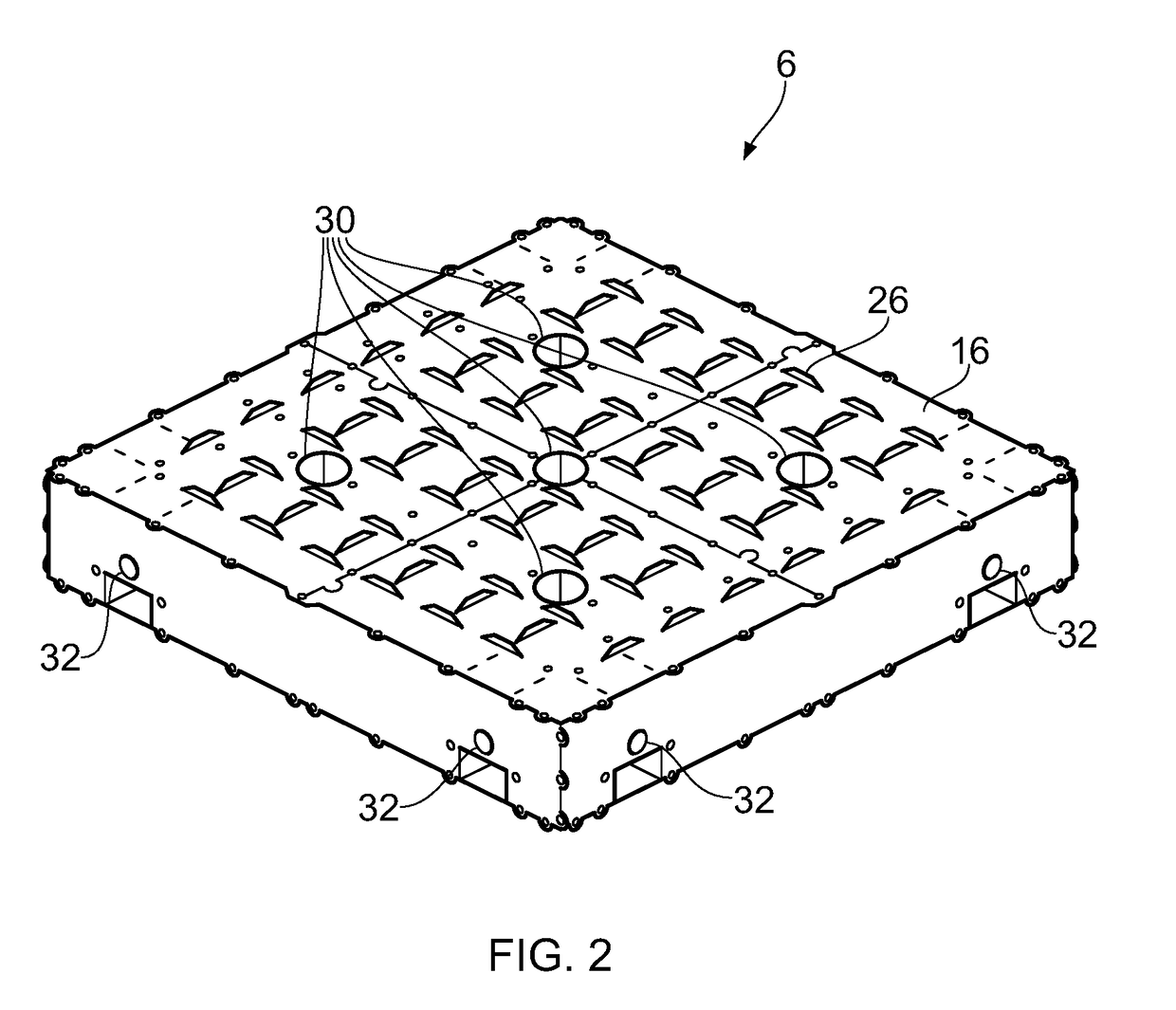
[0037]FIG. 1 shows an insulated container 2 for cooling a heated tooling component 4 (see FIGS. 5A and 5B). The insulated container 2 generally comprises a thermally insulated base 6 and a thermally insulated cover 8, which together form a housing. The thermally insulated cover 8 comprises four thermally insulated side walls 10 and a thermally insulated upper wall 12 connected to the side walls 10. A lower surface 14 (see FIGS. 5A and 5B) of the cover 8 is detachably coupled to an upper surface 16 (see FIG. 2) of the base 6. Consequently, the cover 8 is detachably coupled to the base 6. A vent 18 passes through the upper wall 12. The vent 18 generally comprises an opening 20 passing through the upper wall 12, a valve member 22 and a linear actuator 24.

[0038]FIG. 2 shows the base 6 in isolation. The base 6 comprises a metal exterior and an insulating core. The base 6 is substantially cuboid in shape, has a substantially square profile when viewed from above and is substantially plana...


PUM

PropertyMeasurementUnit
air flow rateaaaaaaaaaa
sizeaaaaaaaaaa
flow areaaaaaaaaaaa

Abstract

Disclosed is an insulated container 2 for cooling a heated tooling component 4. The insulated container 2 comprises: a housing including a thermally insulated base 6, an insulated side wall 10 and an insulated upper wall 12 which define a chamber 36 for receiving the tooling component 4; an inlet port 30 passing through the insulated base 6, the inlet port 30 allowing ambient air to enter the chamber 36; and a vent 18 passing through the insulated upper wall 12, the vent 18 allowing air heated by the heated tooling component 4 to be ejected such that a convective air flow through the chamber 36 cools the tooling component 4, wherein a flow area of the vent 18 can be varied to allow an air flow rate through the chamber 36 to be controlled. There is also disclosed a method of cooling a heated tooling component 4.

Description

CROSS-REFERENCE TO RELATED APPLICATION[0001]This application is based upon and claims the benefit of priority from British Patent Application Number 1621376.1 filed 15 Dec. 2016, the entire contents of which are incorporated by reference.BACKGROUND1. Field of the Disclosure[0002]The disclosure relates to an insulated container for and method of cooling a heated tooling component.2. Description of the Related Art[0003]A variety of hot forming processes are known and currently used in industry. One such hot forming process is superplastic forming (SPF). SPF involves heating sheet metal such that it exhibits superplasticity, and subsequently forming it using techniques normally used for forming plastics. During SPF, in addition to heating the sheet metal itself, it is also necessary to heat the tooling components used to form the sheet metal. This maintains the temperature of the sheet metal whilst it is being formed. However, since the tooling components have non-uniform thickness, af...

Claims


Application Information

Patent Timeline
Patent Type & Authority Applications(United States)
IPC IPC(8): B65D81/38B65D81/26F28F27/02
CPCB65D81/3813B65D81/263F28F27/02F28F2270/00B21D26/031B21D26/055B21D37/16B22C9/065B29C71/02C21D1/84
Inventor SHILTON, CHARLES M.
Owner ROLLS ROYCE PLC
Learn More