
Retro-directive Quasi-Optical System

Active Publication Date: 2018-06-07
TZUANG CHING KUANG C
View PDF0 Cites 7 Cited by
  • Summary
  • Abstract
  • Description
  • Claims
  • Application Information

AI Technical Summary

Benefits of technology

The present invention proposes a system that can interact with objects that are remotely distributed. The system is fast-switching, low-cost, power-efficient, flexible, and high-resolution. It is more suitable for high-frequency EM waves in the millimeter wave or terahertz regime. Overall, the technical effect of the invention is to provide a more efficient and flexible way to interact with remote objects.

Problems solved by technology

Furthermore, the consideration of the size of the lens set, the amount of pixels, and the distribution of the pixels depends on application; but typically, the tradeoff is between resolution and cost.

Method used


Image

  • Retro-directive Quasi-Optical System
  • Retro-directive Quasi-Optical System
  • Retro-directive Quasi-Optical System

Examples


Embodiment Construction

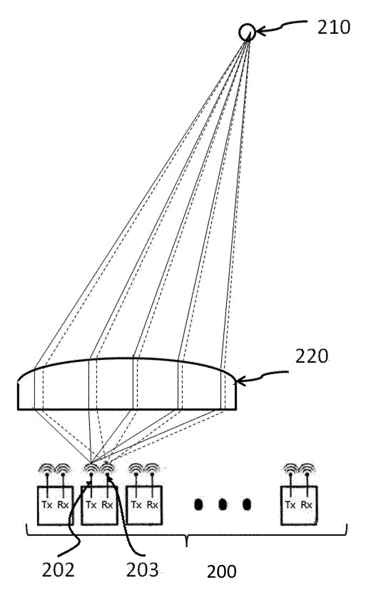
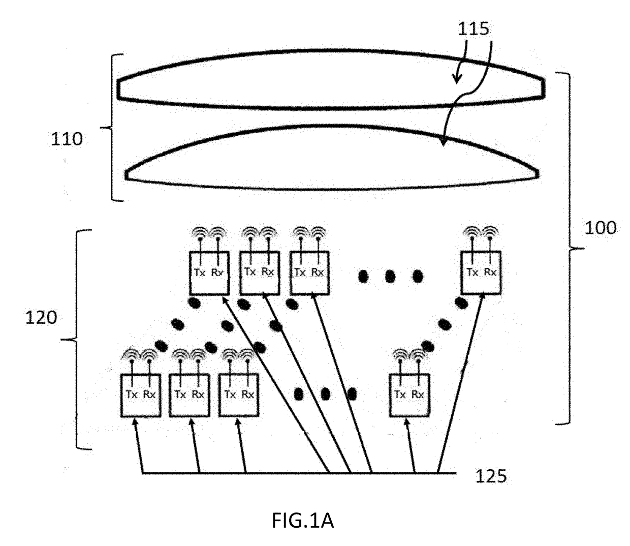
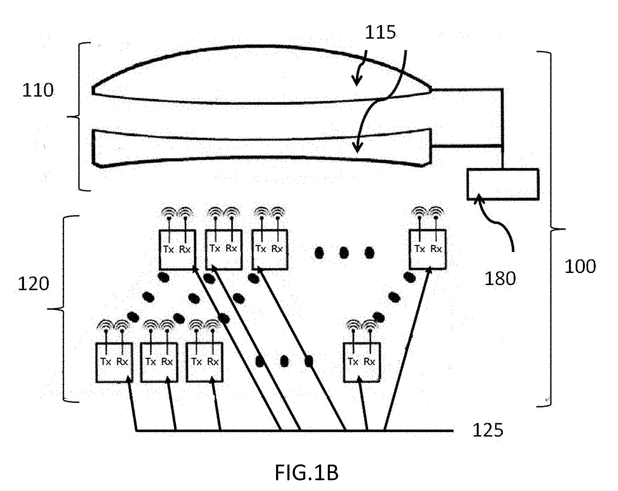
[0015]The invention, as shown in FIG. 1A, is related to a retro-directive quasi-optical system 100 that includes at least a lens set 110 and a pixel array 120, wherein a two-dimensional array resides on a two-dimensional surface is present as an example. The pixel array 120 sets the resolution of the quasi-optical system. The lens set 110 has one or more lens 115, and the pixel array 120 has some pixels 125 wherein each pixel is composed of one or more transmitter (Tx) antennas and one or more receiver (Rx) antennas, which define the locations where EM wave are transmitted and received, and the physical size of each pixel may be defined as the area enclosed by the Tx and Rx antennas. One or more transmitters are connected to the Tx antenna(s) and convert the electrical signals to the outgoing EM waves, and one or more receivers are connected to the Rx antenna(s) and convert the incoming EM waves into the electrical signals. Also, the Tx and Rx may include other circuit elements, suc...


PUM


Abstract

The proposed retro-directive quasi-optical system includes at least a lens set and a pixel array. The lens set is positioned on one side of the pixel array and the lens set instantly establishes retro-directive space channels between the pixels in the pixel array and the object(s) distributed in the accessible space defined by the lens set through infinite or finite conjugation. In the pixel array, a number of pixels are arranged as an array and each pixel is composed of at least one pair of transmitter antenna and receiver antenna. To guarantee that the electromagnetic waves transmitted from a pixel into the accessible space may be reflected back to the receiver of the same pixel, the size of each pixel is not larger than the point-spread spot size defined by the lens set, wherein the point-spread spot size can be contributed either from lens diffraction or aberration.

Description

FIELD OF THE INVENTION[0001]The present invention relates to a retro-directive quasi-optical system, which is capable of interacting with many spatially distributed object(s) simultaneously, especially, the proposed system uses a lens set having one or more lenses to establish the space channels that correlate each, or part, of the objects distributed in space with one or some pixels within a pixel array, wherein each pixel in the pixel array is composed of one or more Tx (transmitter) antennas and one or more Rx (receiver) antennas.BACKGROUND OF THE INVENTION[0002]In modern days, many devices require remote interaction with spatially distributed objects for a number of applications. For example, remote detection of high-resolution imagery, by means of cameras, is indispensable for social media, artificial-intelligence systems, self-driving cars, security tools, and so on. However, light cannot penetrate opaque obstacles, and it can be easily disturbed by fog and rain, or scattered ...

Claims


Application Information

Patent Timeline
IPC IPC(8): H01Q19/06H01Q3/26H01Q15/02H01Q15/14H01Q3/24
CPCH01Q19/062H01Q3/2647H01Q15/02H01Q15/148H01Q3/245H01Q25/007
Inventor TZUANG, LAWRENCE DAH-CHINGTZUANG, CHING-KUANG C.
Owner TZUANG CHING KUANG C
Learn More