System and methods for design, operation and use of the magnetic resonance of the earth for sleep enhancement
a technology of magnetic resonance and earth magnetic resonance, which is applied in the field of system and methods for design, operation and use of the magnetic resonance of the earth for sleep enhancement, can solve the problem that no method suitable for use in the bed while sleeping provides a method, and achieve the effect of promoting sleep and enhancing sleep quality
- Summary
- Abstract
- Description
- Claims
- Application Information
AI Technical Summary
Benefits of technology
Problems solved by technology
Method used
Image


Examples
embodiments
[0093]The narrative progression through the embodiments provides for a detailed description of, and an understanding of the operation, of the invention.
first embodiment
FIG. 1: Proof of Concept
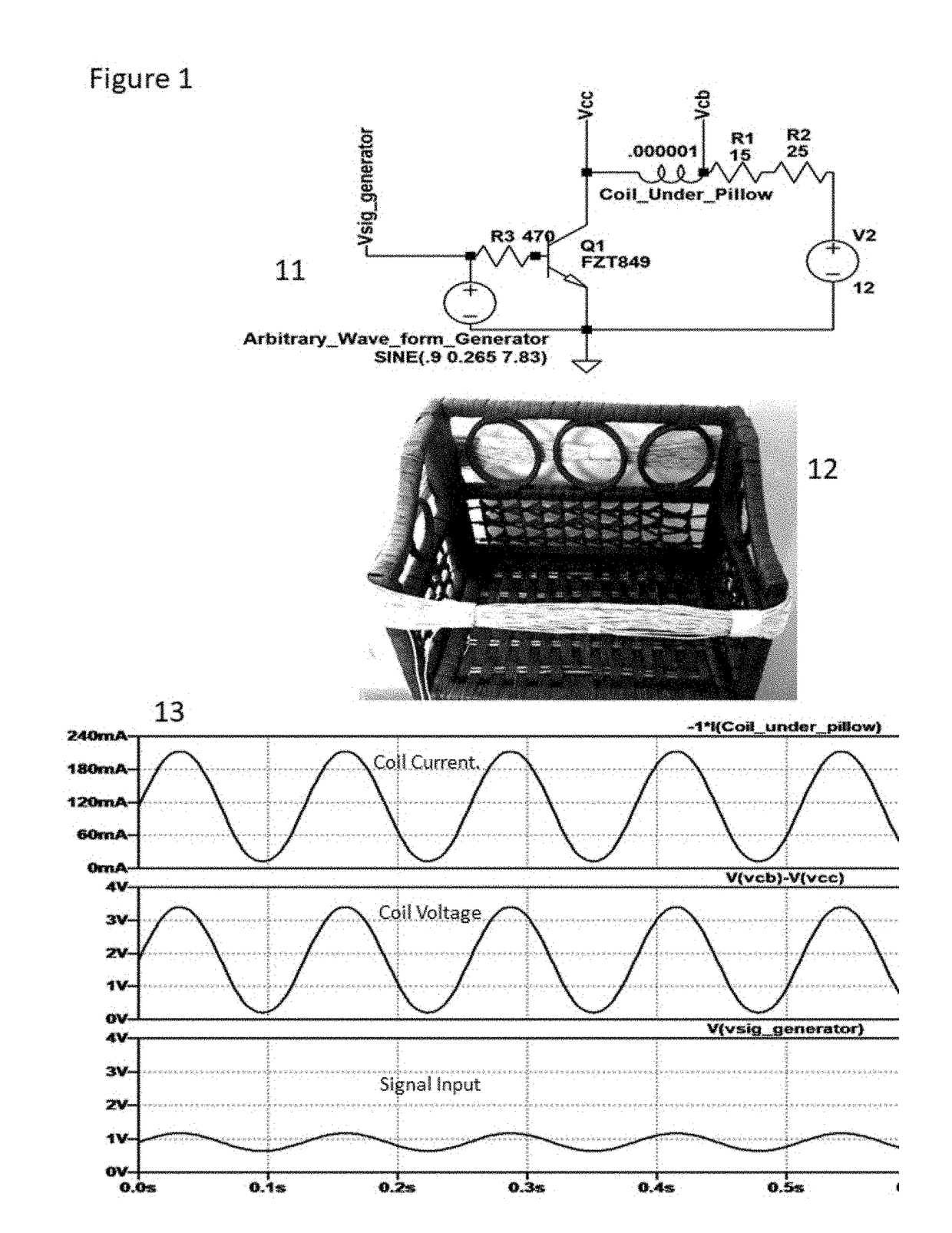
[0094]At the conclusion of the inventor's research, the inventor purchased an “Arbitrary Waveform Generator” capable of producing any wave shape (not just square, sine or triangle). The output was set to 7.83 Hz with a voltage amplitude and DC offset suitable to drive a class-A transistorized amplifier. A single transistor, configured in a common-emitter mode was used to drive a coil placed under the pillow. The voltages can be adjusted on a per-transistor basis making any transistor suitable for carrying 250 mA acceptable to use. FIG. 1, reference number 11, depicts the circuit conceptually for the selected transistor. Values would change for different transistors, but circuit operation would be the same.
[0095]The coil was made from stranded 20-gauge wire in a plastic sheath and was approximately 100 turns, air core, the approximate size of the pillow. This is depicted in FIG. 1, reference number 12. A 25-ohm resistor was placed in series with it to limit cu...
second embodiment
FIG. 2—Astable Multivibrator
[0097]A second embodiment was created consisting of an astable multivibrator circuit (FIG. 2, reference number 21) using two transistors and hand-selected components to account for variances between actual values and recorded component values, as these affect frequencies of operation. The output of each transistor was fed to one side of a hand-made center-tap air core coil. The polarity of the coils was set up such that they would oppose each other. Given that they were never on at the same time they provided for a full-wave magnetic flux signal that alternately aided, then opposed, the Earth's magnetic field. Typical current traces for the respective coils are shown in FIG. 2, reference number 23. The coil was bulky and unsuitable for permanent use, being made of 18-5 conductor. This circuit also eliminated the need for a separate signal generator.
[0098]Coils were then made from 26-gauge enamel coated magnet wire, center-tapped, initially wound on a 5-ga...
PUM
 Abstract
Description
Claims
Application Information
 - R&D
- Intellectual Property
- Life Sciences
- Materials
- Tech Scout
- Unparalleled Data Quality
- Higher Quality Content
- 60% Fewer Hallucinations
Browse by: Latest US Patents, China's latest patents, Technical Efficacy Thesaurus, Application Domain, Technology Topic, Popular Technical Reports.
© 2025 PatSnap. All rights reserved.Legal|Privacy policy|Modern Slavery Act Transparency Statement|Sitemap|About US| Contact US: help@patsnap.com