
Method for controlling beamforming antenna to enhance transmitting/receiving performance and wireless communication device performing the same in tdma-based wireless communication system

a beamforming antenna and wireless communication technology, applied in the field of wireless communication, can solve the problems of two or more ships not being able to share mutual slot occupancy status and plan information, and achieve the effects of enhancing transmitting/receiving performance, reducing error rate, and improving network utilization efficiency

Active Publication Date: 2018-05-31
TONGYANG MOOLSAN CO LTD
View PDF17 Cites 9 Cited by
  • Summary
  • Abstract
  • Description
  • Claims
  • Application Information

AI Technical Summary

Benefits of technology

The patent describes a method for improving the efficiency of a wireless communication network by controlling the direction of a beamforming antenna based on information shared with other stations. This reduces interference and collisions, resulting in better performance and increased range of communication. The method can be applied to both land-based and maritime wireless communication systems, such as VHF data exchange systems.

Problems solved by technology

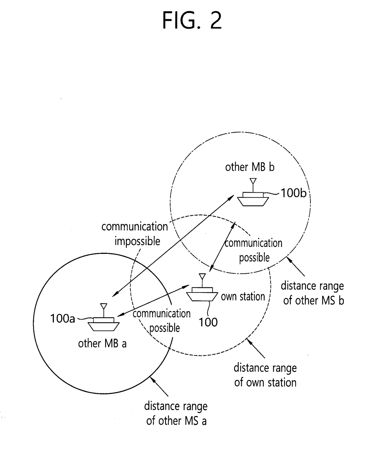
With this scheme, however, in a case in which two or more ships are at a distance or in positions over which two or more ships are unable to perform communication with each other, the two or more ships may not be able to share mutual slot occupancy status and plan information.
However, in the related art maritime communication field, a wireless communication device capable of enhancing communication efficiency using an omnidirectional beamforming antenna has not been disclosed yet.

Method used


Image

  • Method for controlling beamforming antenna to enhance transmitting/receiving performance and wireless communication device performing the same in tdma-based wireless communication system
  • Method for controlling beamforming antenna to enhance transmitting/receiving performance and wireless communication device performing the same in tdma-based wireless communication system
  • Method for controlling beamforming antenna to enhance transmitting/receiving performance and wireless communication device performing the same in tdma-based wireless communication system

Examples


Embodiment Construction

[0045]The present invention may be modified variably and may have various embodiments, particular examples of which will be illustrated in drawings and described in detail. However, it is to be understood that the present invention is not limited to a specific disclosed form, but includes all modifications, equivalents, and substitutions without departing from the scope and spirit of the present invention.

[0046]Terms such as ‘first’, ‘second’, etc., may be used to describe various components, but the components are not to be construed as being limited to the terms. The terms are used only to distinguish one component from another component. For example, the ‘first’ component may be named the ‘second’ component and the ‘second’ component may also be similarly named the ‘first’ component, without departing from the scope of the present invention. The term “and / or” includes a combination of a plurality of relevant items or any one of a plurality of relevant items. It is to be understoo...


PUM


Abstract

Provided are a method for controlling a beamforming antenna to enhance transmitting / receiving performance and a wireless communication device performing the same in a TDMA-based wireless communication system. The wireless communication device includes a beamforming antenna, which is configured with omnidirectional antennas, including a central antenna and a plurality of parasitic antennas and a controller controlling a beamforming direction of the beamforming antenna by analyzing a signal received from other station. The method for controlling a beamforming antenna includes analyzing, by a wireless communication device having a beamforming antenna, which is configured with omnidirectional antennas, including a central antenna and a plurality of parasitic antennas, a signal received from other station to control a beamforming direction of the beamforming antenna.

Description

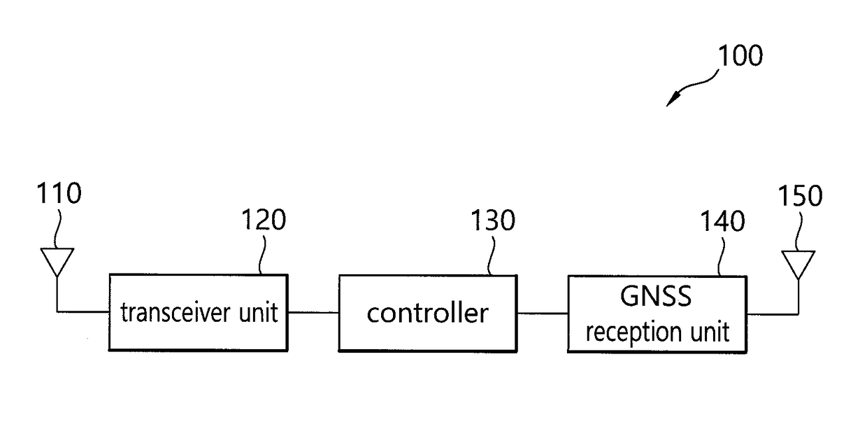
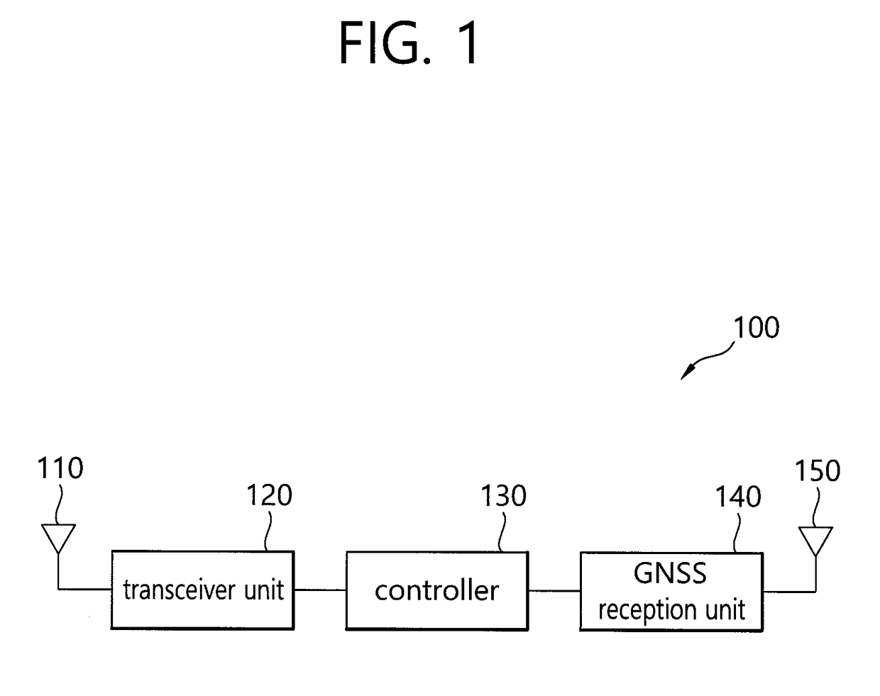
CROSS-REFERENCE TO RELATED APPLICATION[0001]This application claims benefit of priority to Korean Patent Application No. 10-2016-0158643 filed Nov. 25, 2016 in the Korean Intellectual Property Office, the disclosure of which is incorporated herein by reference in its entirety.BACKGROUND OF THE INVENTION1. Field[0002]The present disclosure relates to wireless communication, and more particularly, to methods for controlling a beamforming antenna and a wireless communication device performing the same.2. Description of Related Art[0003]Related art time division multiple access (TDMA) type wireless communication is based on a scheme in which transmission terminals transmit signals using different time slots, thus controlling collision and interference.[0004]FIG. 1 is a schematic configuration diagram of a general TDMA-based wireless communication device 100 having an omnidirectional antenna. Referring to FIG. 1, a general TDMA-based wireless communication device 100 having an omnidirect...

Claims


Application Information

Patent Timeline
Patent Type & Authority Applications(United States)
IPC IPC(8): H04W16/28H04W72/04H04W72/08
CPCH04W16/28H04W72/085H04W72/046H04W72/0446H04B7/0617H04B7/086H04B7/028H04B7/2643
Inventor LEE, JU HWANMOON, HYUNG JIN
Owner TONGYANG MOOLSAN CO LTD
Learn More