
Cutaneous blood flow monitoring device

a monitoring device and blood flow technology, applied in the field of cutaneous blood flow monitoring devices, can solve the problems that non-invasive devices measuring tissue perfusion parameters have not been shown to be useful in determining or diagnosing skin disease or other pathological states in subjects, and achieve the effect of enabling a relative measuremen

Inactive Publication Date: 2018-05-31
VERISKIN INC
View PDF0 Cites 4 Cited by
  • Summary
  • Abstract
  • Description
  • Claims
  • Application Information

AI Technical Summary

Benefits of technology

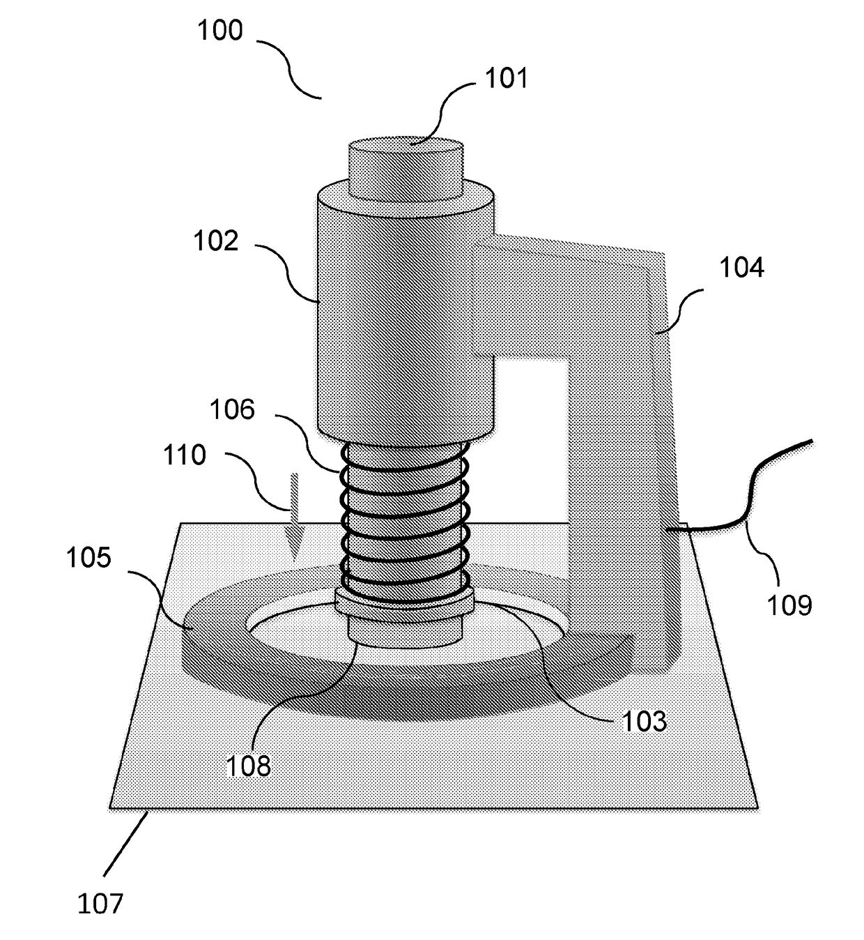
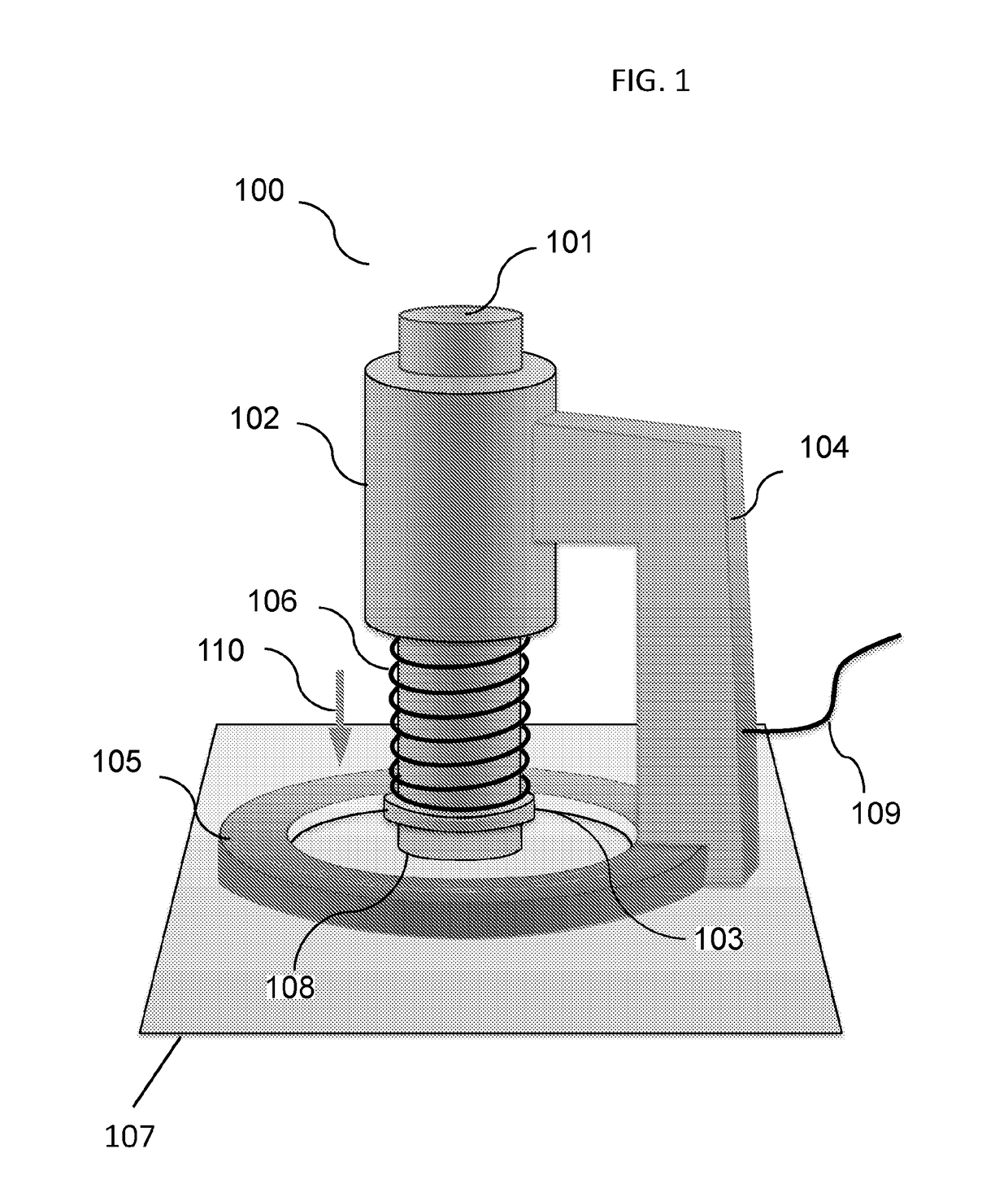
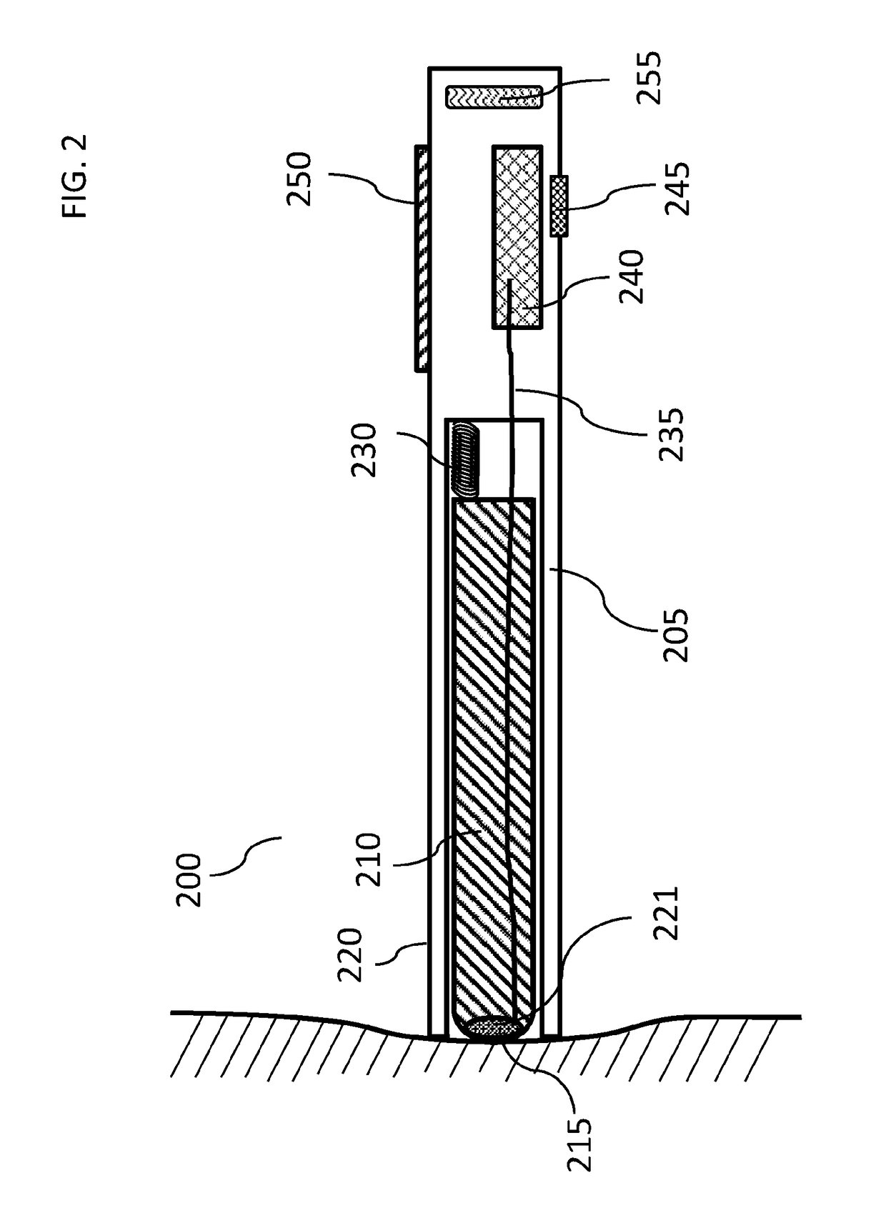
This patent describes a device that is designed to make contact with the skin surface and monitor blood flow through the skin. The device can be held in position by a user's hand and has sensors that can measure blood flow in specific areas. The device is designed to make contact with the skin surface and monitor blood flow through the skin capillaries, which are located just under the skin's surface. The device measures these blood flow parameters in a way that is confined to the skin layer and does not include measurements from deeper subcutaneous tissues. This makes it possible to monitor blood flow without affecting the body as a whole. The device has a concave or non-planar surface to improve contact with the skin. Overall, this device provides a way to accurately measure blood flow in specific areas of the skin.

Problems solved by technology

Although useful as a general assessment of vascular health and vascular system function, non-invasive devices measuring tissue perfusion parameters have not been shown useful for determining or diagnosing skin disease or other pathological states in subjects.

Method used


Image

  • Cutaneous blood flow monitoring device
  • Cutaneous blood flow monitoring device
  • Cutaneous blood flow monitoring device

Examples


example 1

on Assessment

[0190]In this example, a device as disclosed herein may be employed by a clinician to assess a suspect skin lesion, e.g., a mole-like growth, for characteristics associated with a cancerous state.

[0191]The clinician would position the end of the device on a suspected skin lesion, e.g., such that the inner member sensor head was located at the area to be examined. The clinician would then activate the device while maintaining the device against the skin surface. The operational cycle would then automatically occur resulting in measurements being taken automatically by the device. The measurement would then be repeated on the normal-looking skin in the general area of the body where the lesion is located to obtain comparative reference cutaneous blood flow data. Alternatively a second probe would be positioned nearby the lesion and the reference data acquired simultaneously. In another embodiment the probe would contain two independent sensing elements so that the first c...

example 2

Device for Consumer Use

[0194]In this example, a device as disclosed herein may be employed by a consumer to assess a suspect skin lesion, e.g., a mole-like growth, for characteristics associated with a cancerous state.

[0195]The consumer would position the end of the device on a suspected skin lesion, e.g., such that the sensor head was located at the area to be examined. The consumer would then activate the device while maintaining the device against the skin surface. The operational cycle would then automatically occur resulting in measurements being taken automatically by the device. The measurement would then be repeated on normal-looking skin in the general area of the body where the lesion is located to obtain reference data. Alternatively a second probe would be positioned nearby the lesion and the reference data acquired simultaneously. In another embodiment the probe would contain two independent sensing elements so that the first could be positioned over the lesion and the ...


PUM


Abstract

A method and a device for diagnostic of skin cancer and other mammalian skin tissue pathologies are described. The method relies on determination of pathological changes in tissue vascularization and capillary blood flow. The device uses photonic or ultrasound emitters and detectors to characterize temporal and spatial changes in blood flow associated with pulsative actions of the heart.

Description

CROSS-REFERENCE[0001]This application claims the benefit of U.S. Provisional Application No. 62 / 162,597, filed May 15, 2015, which is incorporated herein by reference in its entirety.FIELD OF THE INVENTION[0002]The field of the invention generally relates to the use of spatially resolved measurement of cutaneous blood flow, including dermal capillary flow and perfusion for use in the detection of skin cancer and other mammalian disease states.BACKGROUND OF THE INVENTION[0003]Assessment of skin capillary blood refill rate has been used for determination of health status, primarily for use as an index of whole body shock or whole body dehydration. Typically, such assessment involves determining the refill time of blood vessels and capillaries of cutaneous and subcutaneous tissues following the transitory removal of blood via an applied force. Although useful as a general assessment of vascular health and vascular system function, non-invasive devices measuring tissue perfusion paramet...

Claims


Application Information

Patent Timeline
Patent Type & Authority Applications(United States)
IPC IPC(8): A61B5/0215A61B8/06A61B5/00A61B5/01A61B5/022
CPCA61B5/02152A61B5/441A61B8/06A61B5/7257A61B5/022A61B5/0095A61B5/01A61B5/6843A61B5/0261A61B5/1101A61B5/14539A61B5/444A61B2562/0233A61B2562/046
Inventor CHACHISVILIS, MIRIANASEDMAN, CARL FREDERICKTU, EUGENE
Owner VERISKIN INC
Learn More