
Envelope tracking for high power amplifiers

a high-power amplifier and envelope tracking technology, which is applied in the direction of amplifiers, amplifier types, amplifiers with semiconductor devices/discharge tubes, etc., can solve the problems of reducing the linearity and power delivered changing the compression characteristics of the power amplifier, and increasing the overall cost of the system through the use of regulators

Active Publication Date: 2018-05-17
SKYWORKS SOLUTIONS INC
View PDF2 Cites 51 Cited by
  • Summary
  • Abstract
  • Description
  • Claims
  • Application Information

AI Technical Summary

Benefits of technology

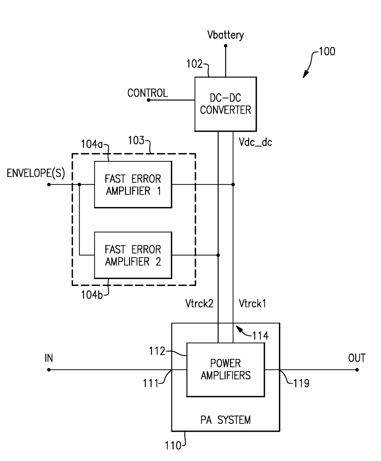
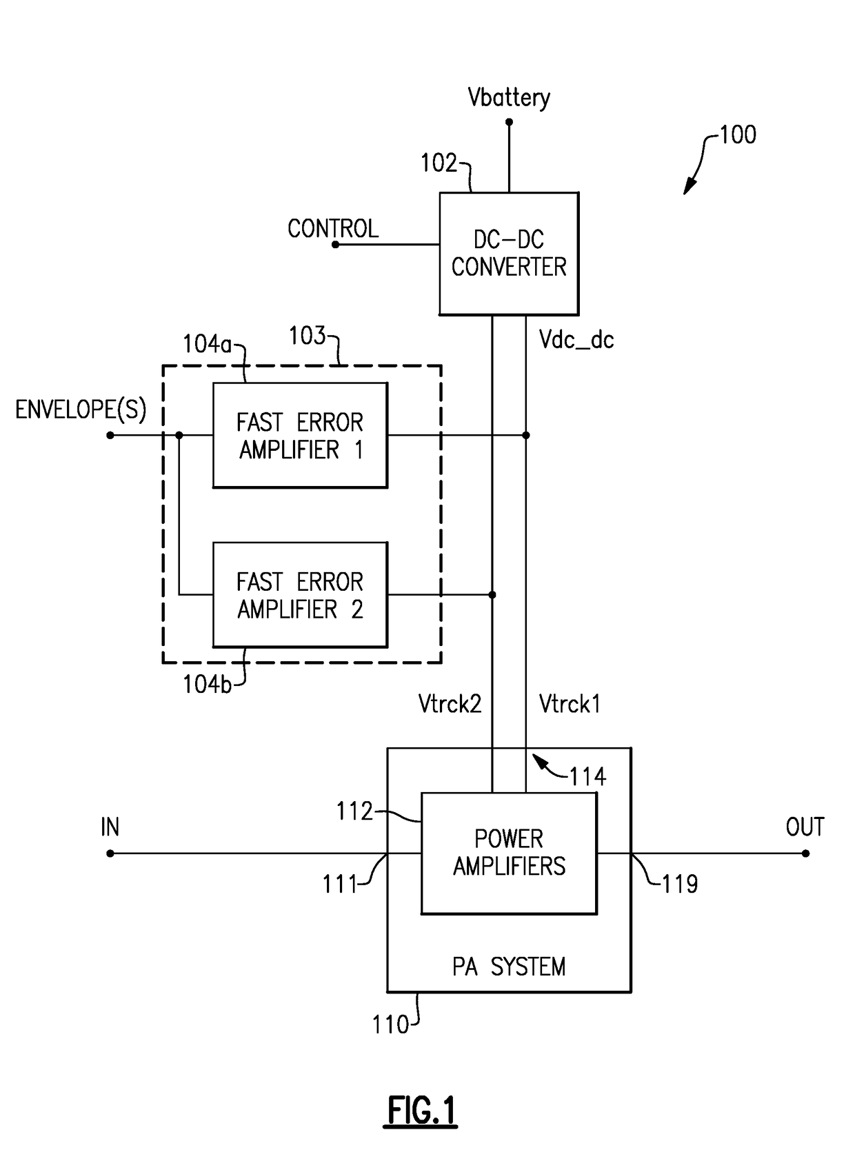
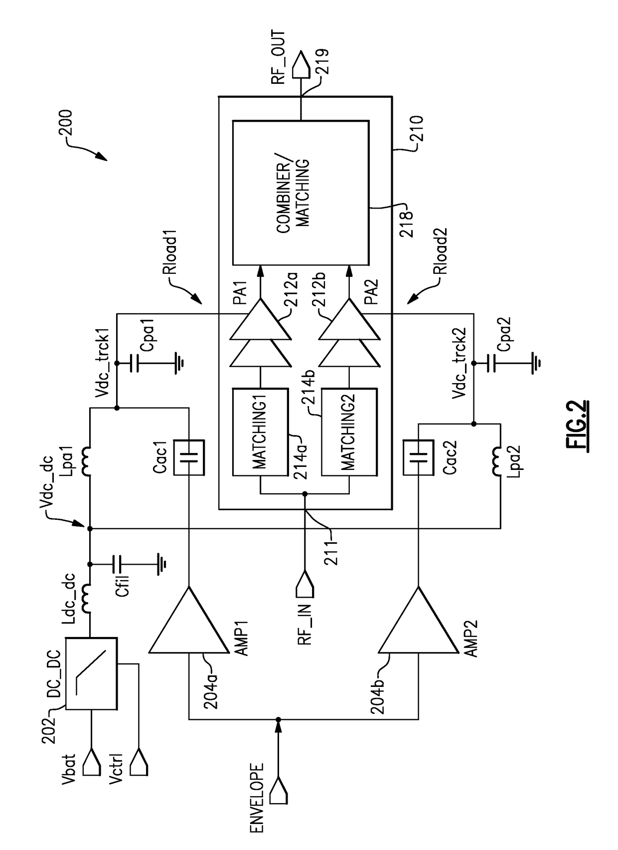
The present patent relates to a wireless communications system that includes an envelope tracking system. The envelope tracking system generates a regulated supply voltage by combining individual outputs of fast error amplifiers with a DC-DC converter. The system also includes a plurality of power amplifiers connected in parallel between a signal input terminal and a signal output terminal, each power amplifier coupled to a fast error amplifier to receive an envelope tracking signal. The power amplifiers amplify a portion of an input signal received at the input terminal so that the power load is divided among them. A combiner combines the amplified signals and generates an output signal. The wireless device also includes an antenna in communication with the combiner to transmit the amplified RF signal. The technical effects of the patent include improved efficiency, reduced harmonics, improved linearity, and improved bandwidth.

Problems solved by technology

Failure to employ such a regulator can result in a change in the compression characteristics of the power amplifier and degrade its linearity and the power delivered.
However, use of a regulator increases the overall cost of the system.
Furthermore, supplying just a fixed voltage to power amplifier systems can result in decreases in efficiency.

Method used


Image

  • Envelope tracking for high power amplifiers
  • Envelope tracking for high power amplifiers
  • Envelope tracking for high power amplifiers

Examples


Embodiment Construction

[0028]The headings provided herein, if any, are for convenience only and do not necessarily affect the scope or meaning of the claimed invention.

[0029]Power amplifier systems are often powered using a supply voltage (e.g., from a battery). In some implementations, the voltage from the battery is regulated (e.g., with a buck converter or a boost converter) to a fixed value to compensate for variations in the voltage output from the battery due to manufacturing variation, age, temperature, discharge or other effects. Failure to employ such a regulator can result in a change in the compression characteristics of the power amplifier and degrade its linearity and the power delivered. However, use of a regulator increases the overall cost of the system. Furthermore, supplying just a fixed voltage to power amplifier systems can result in decreases in efficiency. To address such issues, power amplifier systems can employ envelope tracking to improve efficiency and linearity.

[0030]Envelope t...


PUM


Abstract

Disclosed herein are circuits, devices and methods that address challenges associated with power amplifier systems. A power amplifier system includes two or more fast error amplifiers coupled to corresponding power amplifiers. The fast error amplifiers are configured to generate envelope tracking signals based on a signal envelope, the envelope tracking signals modifying a DC-DC regulated voltage from a DC-DC converter to more efficiently operate the power amplifiers. By splitting the envelope tracking between two or more fast error amplifiers and amplification between corresponding two or more power amplifiers, the power, frequency or bandwidth, linearity, signal-to-noise ratio, efficiency, or the like of the power amplifier system can be improved. Wireless communications configurations with such power amplifier systems can provide uplink carrier aggregation and / or cellular signals based on standards and protocols that require increased bandwidth and / or power.

Description

CROSS-REFERENCE TO RELATED APPLICATIONS[0001]This application claims priority to U.S. Provisional Application Nos. 62 / 421,076 filed Nov. 11, 2017 and entitled “ENVELOPE TRACKING FOR HIGH POWER AMPLIFIERS,” which is expressly incorporated by reference herein in its entirety for all purposes.BACKGROUNDField[0002]The present disclosure generally relates to power supplies for power amplifier systems and more particularly to power supplies that employ envelope tracking to improve power amplifier performance.Description of Related Art[0003]Power amplifier systems are often powered using a supply voltage (e.g., from a battery). In some implementations, the voltage from the battery is regulated (e.g., with a buck converter or a boost converter) to a fixed value to compensate for variations in the voltage output from the battery due to manufacturing variation, age, temperature, discharge or other effects. Failure to employ such a regulator can result in a change in the compression characteri...

Claims


Application Information

Patent Timeline
Patent Type & Authority Applications(United States)
IPC IPC(8): H03F1/02H04B1/04H03F3/24H03F3/217
CPCH03F1/0227H04B1/0483H03F3/24H03F3/2176H03F2200/102H03F1/32H03F1/223H03F3/245H03F3/3022H03F3/45206H03F2200/451
Inventor BALTEANU, FLORINEL G.DROGI, SERGE FRANCOISJIN, BOSHIDICARLO, PAUL T.
Owner SKYWORKS SOLUTIONS INC
Learn More