Electronic vacuum regulator device

a vacuum regulator and electronic technology, applied in the direction of suction drainage containers, fluid pressure control, instruments, etc., can solve the problems of caregivers having to monitor, caregivers having to visually inspect the trap, and further complicate the operation of the vacuum system

Active Publication Date: 2018-04-19
MEDTEC MEDICAL INC
View PDF2 Cites 17 Cited by
  • Summary
  • Abstract
  • Description
  • Claims
  • Application Information

AI Technical Summary

Problems solved by technology

Thus, the prior art vacuum withdrawal systems are all mechanical in nature, and require competing tasks of the caregiver to set the vacuum to the appropriate level.
To further complicate operation of the vacuum system, often a patient's treatment requires tapering maximum levels of vacuum pressure.
Another drawback of current vacuum withdrawal systems is that the caregiver must monitor the level of the exudate in the canister to avoid overfilling.
However, a further drawback of current vacuum withdrawal systems is that the caregiver must visually inspect whether the trap has been contaminated with exudate.

Method used


Image

  • Electronic vacuum regulator device
  • Electronic vacuum regulator device
  • Electronic vacuum regulator device

Examples


Embodiment Construction

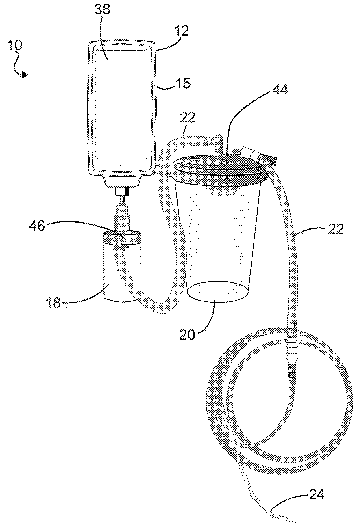
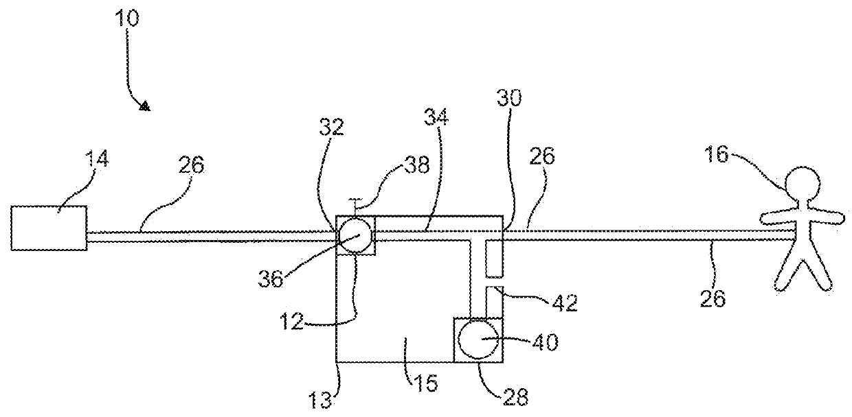
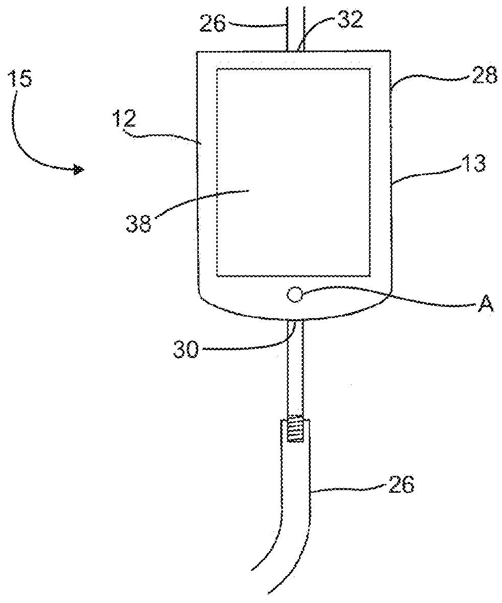
[0019]Referring to FIGS. 1 and 2, a vacuum withdrawal system is indicated generally at 10, and includes a vacuum regulator 12 that is attached upstream of the central vacuum source 14 (seen in FIG. 2) to provide a regulated source of vacuum to the patient 16 (also seen in FIG. 2). As used herein, the source of vacuum will be a downstream location and the patient cavity will be an upstream location, such that the terms “upstream” and “downstream” will reference the flow of fluid in the direction from the patient 16 toward the central vacuum source 14.

[0020]As seen in FIG. 1, upstream of the vacuum regulator 12 is a trap 18 that prevents exudate from entering the vacuum regulator, and upstream of the trap is a collection canister 20 that receives and collects the exudate from the patient 16. Connection tubing 22 connects the trap 18 and the collection canister 20, such that they are in fluid communication. Upstream of the collection canister 20 is a suction device 24, such as a cannul...


PUM


Abstract

A vacuum regulator device having a vacuum regulator and a vacuum gauge on a housing line that is configured to be in fluid communication with a patient include an electronic valve that selectively opens and closes the housing line. The vacuum gauge is located between the vacuum regulator and the patient and includes an electronic flow sensor upstream. The electronic flow sensor provides feedback to the vacuum regulator.

Description

CROSS-REFERENCE TO RELATED APPLICATIONS[0001]This application claims priority under 35 U.S.C. 119(e) to U.S. Provisional Patent Application No. 62 / 409,952, filed Oct. 19, 2016, entitled “ELECTRONIC VACUUM REGULATOR DEVICE,” which is herein incorporated by reference in its entirety.FIELD OF THE INVENTION[0002]The present disclosure relates to vacuum regulators that are used to withdraw fluids from a patient.BACKGROUND OF THE INVENTION[0003]Vacuum withdrawal systems are used in a hospital setting to withdraw fluids from a cavity of a patient. Hospitals typically have a central vacuum source on site, and a series of lines from the central vacuum source to various operating rooms and patient rooms throughout the hospital. In these rooms, a vacuum regulator is attached to the central vacuum source, typically at a wall connection, to provide a regulated source of vacuum to the patient. Specifically, the vacuum regulators are used to regulate for a specific level of vacuum pressure that is...

Claims


Application Information

Patent Timeline
Patent Type & Authority Applications(United States)
IPC IPC(8): A61M1/00
CPCA61M1/0035A61M1/0029A61M1/0001A61M2205/3334A61M2205/18A61M2202/04A61M2205/505A61M2205/3553A61M2205/50A61M2205/3393G05D16/2013G05D16/024A61M1/734A61M1/74A61M1/743A61M1/60A61M2205/3337A61M1/732A61M1/76A61M1/80
Inventor KILCRAN, MICHAEL D.
Owner MEDTEC MEDICAL INC
Why Eureka
Try Eureka