Motor and rotor thereof

a technology of rotor and motor, which is applied in the direction of dynamo-electric machines, magnetic circuit rotating parts, and magnetic circuit shape/form/construction, etc., to achieve the effect of preventing the magnet from breaking

Inactive Publication Date: 2018-04-05
JOHNSON ELECTRIC SA
View PDF0 Cites 6 Cited by
  • Summary
  • Abstract
  • Description
  • Claims
  • Application Information

AI Technical Summary

Benefits of technology

[0018]The inner circumference of the cover portion is greater than the length of the envelope line formed by the outer circumferential surfaces of the magnets and common tangents of the outer circumferential surfaces of adjacent magnets, and is less than the circumference of the circumscribed circle of the magnets, thereby guaranteeing the fixing strength of the magnets while also preventing the magnets from breaking.

Problems solved by technology

Therefore, how to arrange the protective tube to guarantee the fixing strength of the magnets to prevent movement of the magnets without breaking the magnets due to overlarge stress has become an issue to be solved in the industry.

Method used


Image

  • Motor and rotor thereof
  • Motor and rotor thereof
  • Motor and rotor thereof

Examples


Embodiment Construction

[0027]Embodiments of the present invention will be described in greater detail with reference to the drawings. It should be noted that the figures are illustrative rather than limiting. The figures are not drawn to scale, do not illustrate every aspect of the described embodiments, and do not limit the scope of the present disclosure. Unless otherwise specified, all technical and scientific terms used in this disclosure have the ordinary meaning as commonly understood by people skilled in the art.

[0028]When an element or a layer is referred to as “being connected to” another element or layer, the element or the layer can be located directly on another element or layer so as to be connected to another element or layer, or there may be an intermediate element and / or layer. In contrast, when an element is referred to as “being directly connected” to another element or layer, there is no intermediate element or layer.

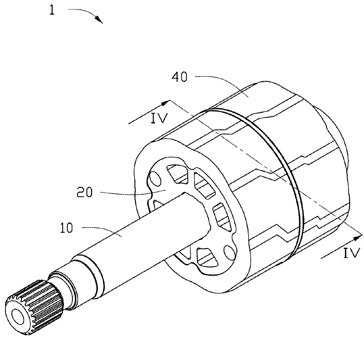
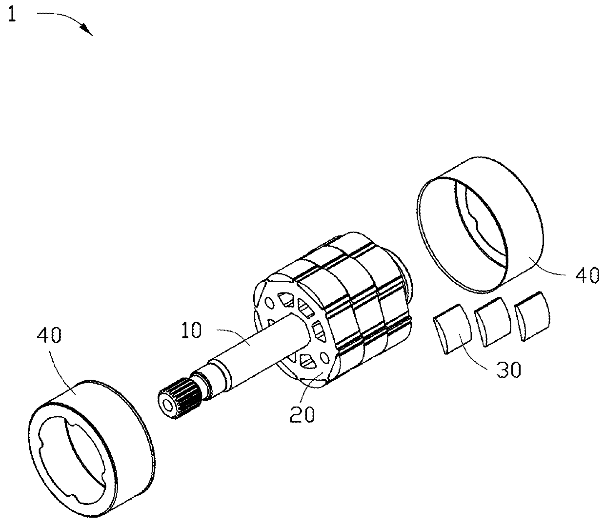
[0029]FIGS. 1 and 2 are schematic views of a rotor in accordance with ...


PUM


Abstract

A rotor includes a rotor core and a plurality of magnets. The magnets are fixed on an outer circumferential surface of the rotor core. The rotor further includes at least one protective tube. The protective tube includes a cover portion. An inner circumference of the cover portion is greater than a length of an envelope line formed by outer circumferential surfaces of the magnets and common tangents of the outer circumferential surfaces of adjacent magnets, and is less than a circumference of a circumscribed circle of the magnets. The cover portion covers the magnets in a circumferential direction, thereby guaranteeing the fixing strength of the magnets while also preventing the magnets from breaking.

Description

CROSS REFERENCE TO RELATED APPLICATIONS[0001]This non-provisional patent application claims priority under 35 U.S.C. § 119(a) from Patent Application No. 201610873290.X filed in The People's Republic of China on Sep. 30, 2016.FIELD OF THE INVENTION[0002]The present invention relates to a rotor and a motor including the rotor, and in particular to a motor suitable for an electric power steering system and a rotor of the motor.BACKGROUND OF THE INVENTION[0003]Currently, a plurality of magnets is arranged on an outer circumferential surface of a rotor core. A non-magnetic protective tube is provided to cover the magnets in order to prevent the plurality of magnets from flying away from the rotor core when the rotor rotates. Therefore, how to arrange the protective tube to guarantee the fixing strength of the magnets to prevent movement of the magnets without breaking the magnets due to overlarge stress has become an issue to be solved in the industry.SUMMARY OF THE INVENTION[0004]Thus ...

Claims


Application Information

Patent Timeline
Patent Type & Authority Applications(United States)
IPC IPC(8): H02K1/28H02K1/27H02K5/04H02K5/02
CPCH02K1/28H02K1/2786H02K5/04H02K5/02H02K1/22H02K1/278H02K1/2791H02K2213/03
Inventor SUN, NINGQIN, RUI FENGZHOU, XIAO HONGLIU, XING
Owner JOHNSON ELECTRIC SA
Why Eureka
Try Eureka