Tire vulcanizing apparatus

a vulcanizing apparatus and tire technology, applied in the field of tire vulcanizing apparatus, can solve the problems of reducing the efficiency of vulcanizing apparatus, and causing uneven temperature distribution, etc., to achieve suppressed vulcanization unevenness, easy discharge of drain, and suppressed uneven vulcanization

Active Publication Date: 2018-03-29
SUMITOMO RUBBER IND LTD
View PDF0 Cites 0 Cited by
  • Summary
  • Abstract
  • Description
  • Claims
  • Application Information

AI Technical Summary

Benefits of technology

The present invention proposes a tire vulcanizing apparatus with a vulcanizing bladder having a double structure. The invention aims to address issues of fluid flow and drainage due to partial contact between the inner and outer bladders, and to prevent vulcanization unevenness. The invention achieves this by supplying steam between the inner and outer bladders, reducing the likelihood of drain generation and ensuring uniform temperature distribution on the tire. The invention also includes a guide groove to secure a gap between the two bladders and prevent flow failure and discharge failure, further promoting smooth vulcanization process. The technical effects are a reduced likelihood of drain generation, easy discharge of drain, and uniform temperature distribution on the tire, resulting in a suppression of vulcanization unevenness.

Problems solved by technology

However, since the tire vulcanizing apparatus of Patent Document 1 sequentially supplies steam to the entire inside of the vulcanizing bladder, it requires a lot of energy.
Further, this tire vulcanizing apparatus does not solve the problem of the drain staying in a lower part of the vulcanizing bladder.
When it actually happens, a path of the steam as a heat source is partially blocked, therefore, unevenness in the temperature distribution is induced.
Further, the contact of the inner and the outer bladders hinders the discharge of the drain.
Thereby, it is possible that an effect of suppressing vulcanization unevenness by the double structure is not sufficiently exerted.

Method used


Image

  • Tire vulcanizing apparatus
  • Tire vulcanizing apparatus
  • Tire vulcanizing apparatus

Examples


working example (example)

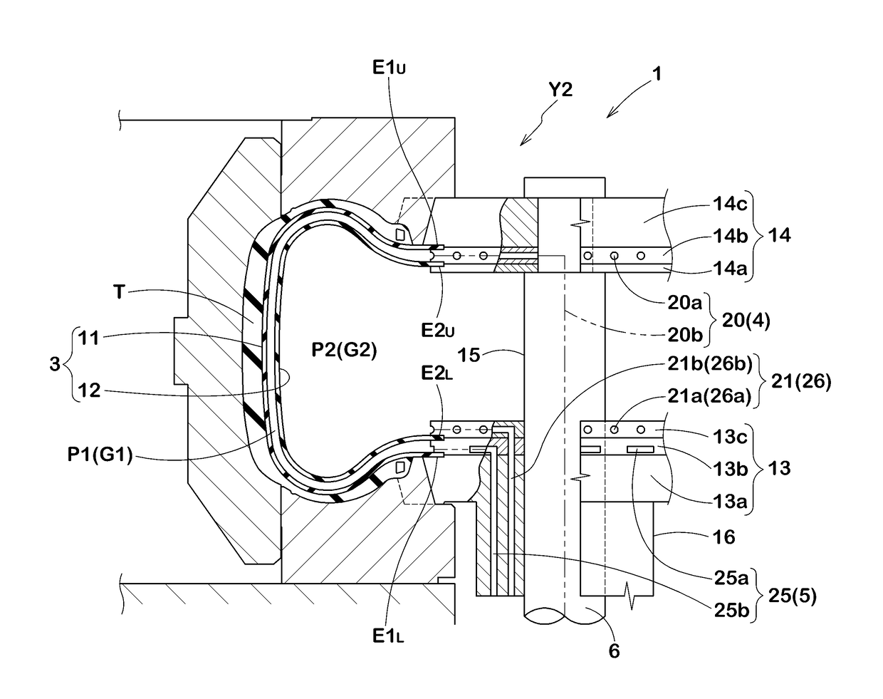
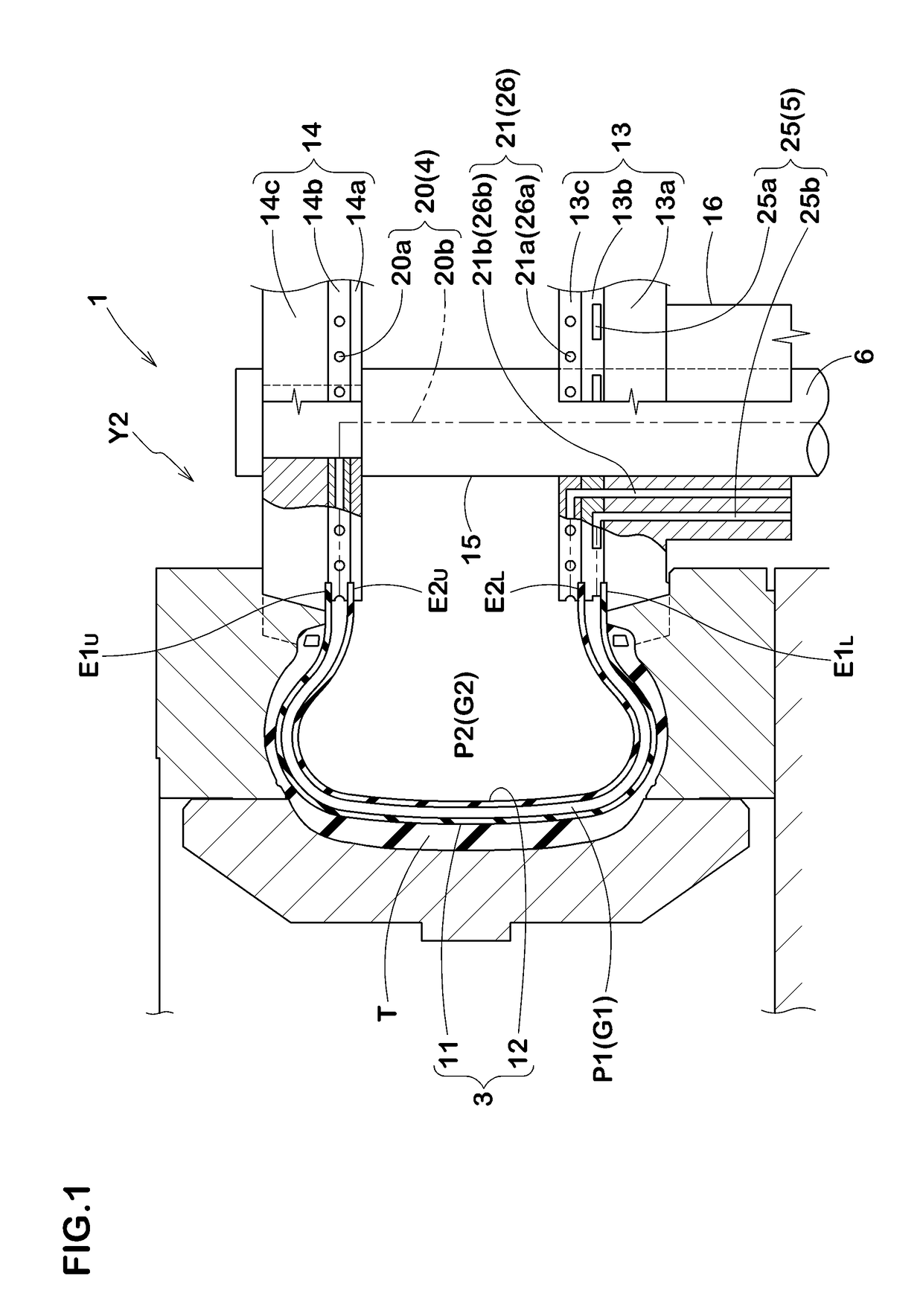
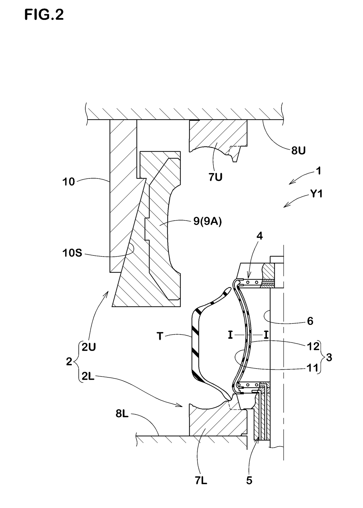
[0051]Unvulcanized tires of size 205 / 60R16 were vulcanization molded using a tire vulcanizing apparatus having structure shown in FIGS. 1 and 2, and having a vulcanizing bladder according to specifications shown in Table 1. Then, the variation (σ) of vulcanization amount among different parts of the test tires was evaluated.

[0052]Note that the vulcanizing bladders of reference and examples each have the double structure including the first bladder and the second bladder, and they differ only as to whether they have the guide grooves or not. The tires as the examples are provided with the guide grooves on the outer circumferential surfaces of the second bladders. Further, in order to prevent decrease in durability due to the guide grooves, in each of the examples, the bladder is formed thicker by the groove depths (H) of the guide grooves.

[0053]Common specifications are as follows.

[0054]The angles θ of the guide grooves with respect to the tire axial direction line: 0 degrees

[0055]Th...


PUM

PropertyMeasurementUnit
groove widthaaaaaaaaaa
anglesaaaaaaaaaa

Abstract

A vulcanizing bladder 3 comprises a first bladder 11 configured to contact with an inner circumferential surface of an unvulcanized tire (T) and a second bladder 12 arranged inside the first bladder 11. A first fluid G1 is to be supplied between the first bladder 11 and the second bladder 12, and a second fluid G2 is to be supplied to an inside of the second bladder 12. At least one of an inner circumferential surface 11s of the first bladder 11 and an outer circumferential surface 12s of the second bladder 12 is provided with a guide groove 31 extending in a tire axial direction through which the first fluid G1 can pass.

Description

TECHNICAL FIELD[0001]The present invention relates to a tire vulcanizing apparatus having a vulcanizing bladder with a double structure.BACKGROUND ART[0002]Conventionally, a tire vulcanizing apparatus for vulcanizing an unvulcanized tire by using a vulcanizing bladder is known. In this type of tire vulcanizing apparatus, for example, a heated fluid is supplied into the vulcanizing bladder to inflate the vulcanizing bladder.[0003]For such fluid, steam is used from a point of view of cost and heat transfer performance, for example. However, when heat is transferred to the unvulcanized tire via the vulcanizing bladder, the steam is condensed to become drain and it is possible that the drain stays in the vulcanizing bladder.[0004]Drain like this decreases temperature of the unvulcanized tire at a part in contact with the drain of the bladder relative to the temperature of the other part of the unvulcanized tire. Therefore, vulcanization unevenness occurs, which tends to cause imbalance ...

Claims


Application Information

Patent Timeline
Patent Type & Authority Applications(United States)
IPC IPC(8): B29D30/06B29C43/36
CPCB29D30/0654B29D30/0606B29C43/3642B29D2030/0616B29D2030/0657B29D2030/0659B29C2043/3649B29D30/0601B29D2030/0655
Inventor TANAKA, TAKASHI
Owner SUMITOMO RUBBER IND LTD
Why Eureka
Try Eureka