Power converter
a power converter and converter technology, applied in the field of main converters, can solve the problems of much more expensive type of phase selective switchgear than a usual one, and achieve the effect of reducing the amount of additional hardwar
- Summary
- Abstract
- Description
- Claims
- Application Information
AI Technical Summary
Benefits of technology
Problems solved by technology
Method used
Image

Examples
first embodiment
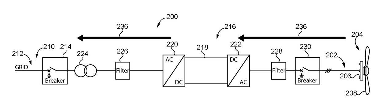
[0046]FIG. 3 shows a main converter 200 according to a The main converter 200 is connected on its generator side 202 to a power plant 204 for regenerative energy having a generator 206 and a wind turbine 208. On its power grid side 210, the main converter 200 is connected to a power grid 212. The power grid 212 in this embodiment is a mid-range voltage power grid with a voltage of 10 to 30 kV.
[0047]The main converter 200 of the first embodiment comprises a grid breaker 214 provided at the power grid side 210 of the main converter 200 and one converter path 216. The converter path 216 comprises a DC link 218, a grid side converter 220 and a generator side converter 222, both connected to the DC link 218. The generator side converter 222 converts AC provided from the generator 206 of the power plant into DC for the DC link 218. The grid side converter 220 converts DC from the DC link 218 into AC. Generator and grid side converter 220, 222 have semiconductor components including diode...
third embodiment
[0056]The main converter 200 according to a second and third embodiment is connected on its generator side 202 to a power plant 204 for regenerative energy having a generator 206 and a wind turbine 208. On its power grid side 210, the main converter 200 is connected to a power grid 212. The main converter 200 further comprises a grid breaker 214 provided at the power grid side 210 of the main converter 200.
[0057]The main converter 200 according to a second and third embodiment comprises two converter paths 216. Each converter path 216 comprises a DC link 218, a god side converter 220 and a generator side convener 222, both connected to the DC link 218. Furthermore, each converter path 216 comprises a high frequency grid filter 226 provided at the power grid side 210 of the grid side converter 222. At the generator side 202, each converter path 216 comprises a dV / dt filter 228 for limiting the slew rate and a generator breaker 230.
[0058]A main transformer 224 is provided between the ...
second embodiment
[0060]First, the second embodiment is described with reference to FIG. 4. Energy flow during pre-charge is indicated by arrows 236. Before closing the grid breaker 214, energy is provided from the power plant 204 via the generator side converter 222 to the two converter paths 216 for pre-charging all components Of the converter paths 216. The energy is provided directly from the power plant 204 to the respective generator side converters 222 of the two converter paths 216, so that both converter paths 216 are pre-charged in parallel. This includes in both cases pre-charging the respective DC links 218 as well as providing energy via the grid side converters 220 to the high frequency grid filters 226. Finally, also the main transformer 224 is pre-charged based on the energy provided via the two converter paths 216. After pre-charging has finished, the grid breaker 214 is closed and the main converter 200 is connected to the power grid 212. Thereby, also the power plant 204 is connect...
PUM
 Abstract
Description
Claims
Application Information
 - R&D
- Intellectual Property
- Life Sciences
- Materials
- Tech Scout
- Unparalleled Data Quality
- Higher Quality Content
- 60% Fewer Hallucinations
Browse by: Latest US Patents, China's latest patents, Technical Efficacy Thesaurus, Application Domain, Technology Topic, Popular Technical Reports.
© 2025 PatSnap. All rights reserved.Legal|Privacy policy|Modern Slavery Act Transparency Statement|Sitemap|About US| Contact US: help@patsnap.com