
Heating appliance structure

a technology for heating appliances and structures, applied in water heaters, fluid heaters, light and heating equipment, etc., can solve the problems of common drawbacks of heating appliances of the prior, shortcoming, etc., and achieve the effect of resolving the shortcomings of wasting energy resources and time consumption

Inactive Publication Date: 2018-03-08
LIN CHIN TIEN
View PDF30 Cites 1 Cited by
  • Summary
  • Abstract
  • Description
  • Claims
  • Application Information

AI Technical Summary

Benefits of technology

The heating appliance structure aims to allow quick heating of a small amount of water for use by the user. This avoids heating the entire cylinder, which helps save energy resources and time consumption while waiting for hot water.

Problems solved by technology

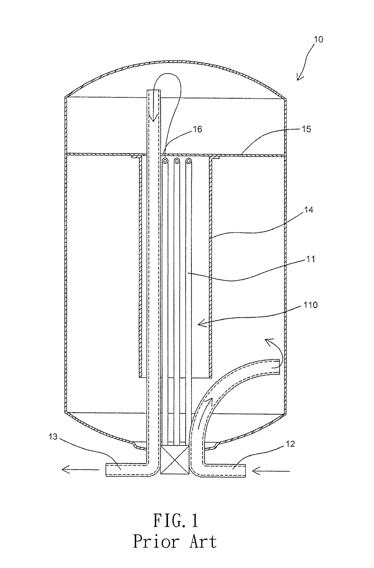
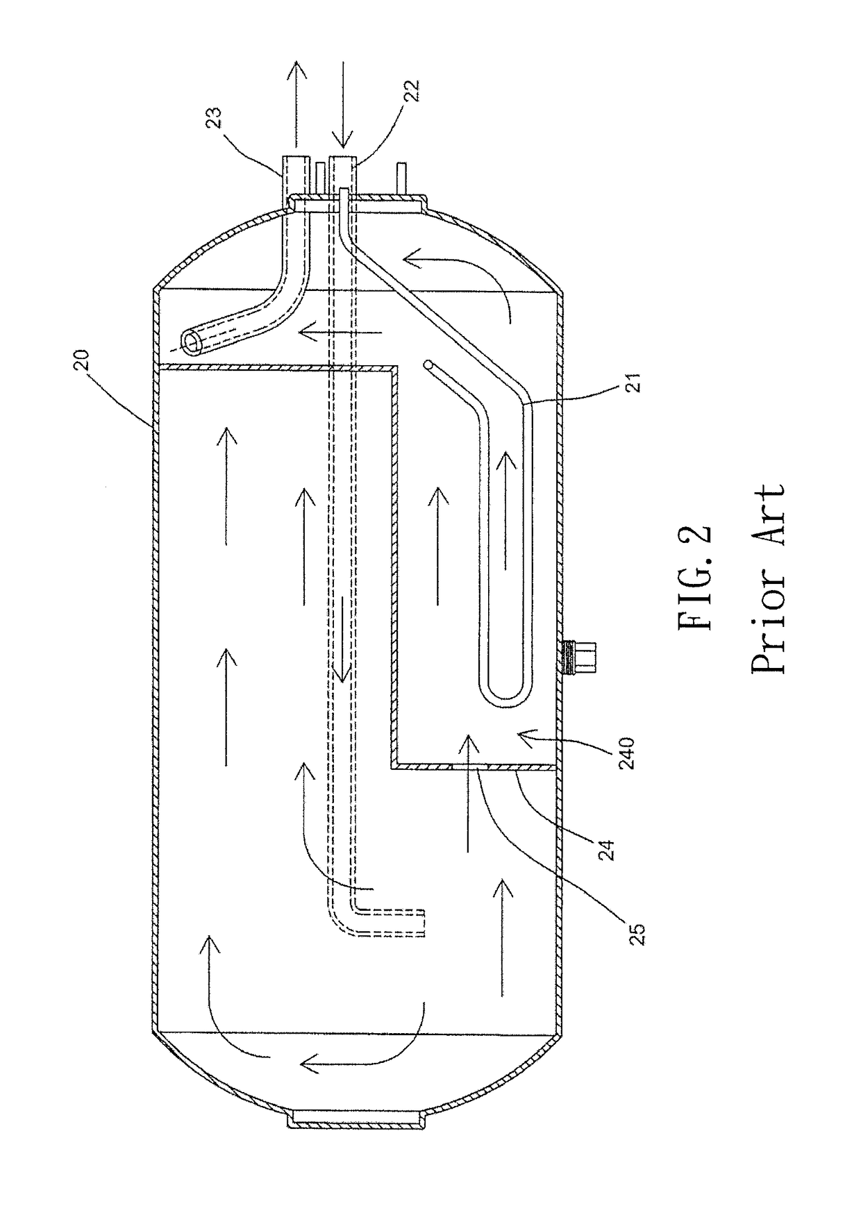
Heating appliances of the prior art waste energy primarily because a partition in a heating area is not able to fully achieve the function of storing heat and blocking energy dissipation.
And this shortcoming is a common drawback of heating appliances of the prior art.

Method used


Image

  • Heating appliance structure
  • Heating appliance structure
  • Heating appliance structure

Examples


Embodiment Construction

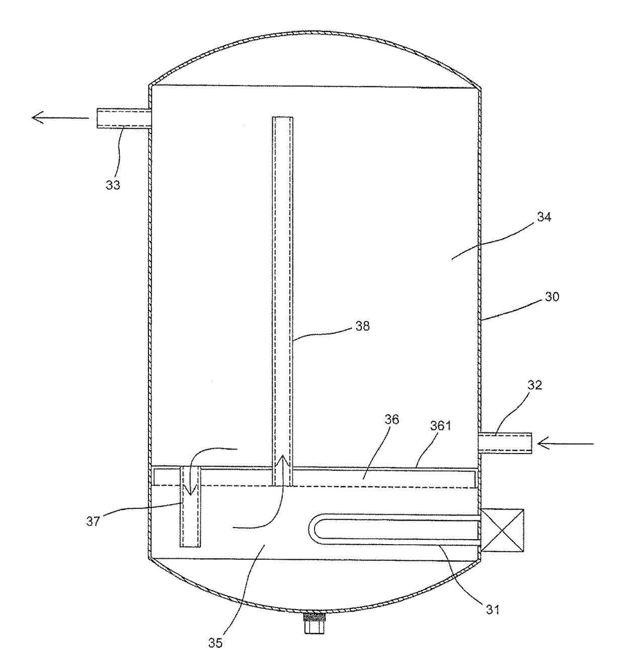
[0024]Referring to FIG. 3, which depicts the first embodiment of a heating appliance structure of the present invention comprising a cylinder 30, a heating pipe 31, a water inlet pipe 32, a water outlet pipe 33, a water storage area 34, and a heating area 35. The cylinder 30 is able to store water, and the interior of the cylinder 30 is partitioned into the heating area 35 and the water storage area 34. The heating pipe 31 extends into the heating area 35 of the cylinder 30, the water inlet pipe 32 channels water into the water storage area 34 within the cylinder 30 from the exterior thereof, and the water outlet pipe 33 channels out heated water from the cylinder 30 to the exterior of the cylinder 30 using the water outlet pipe 33. The heating area 35 is provided with the heating pipe 31 for conducting heat thereto, and an upper portion of the heating area 35 is provided with a heat flow conduit 38, which extends to the water outlet pipe 33 for channeling out heated water to the ex...


PUM


Abstract

A heating appliance structure is provided, including: a cylinder, provided with a heating area and a water storage area; a heat-isolating portion, defining the heating area having an opening in the water storage area and entirely located within the water storage area, the at least one gap being part of the water storage area and directly communicating with the heating area; a heating pipe, wherein the heating pipe extends into the heating area and is located entirely within the heating area; a water inlet pipe, wherein the water inlet pipe channels water into the water storage area within the cylinder from an exterior of the cylinder; a water outlet pipe, wherein the water outlet pipe channels out heated water from the cylinder to the exterior of the cylinder.

Description

BACKGROUND OF THE INVENTIONField of the Invention[0001]This application is a Continuation-in-Part of application Ser. No. 14 / 876147, filed on Oct. 6, 2015, for which priority is claimed under 35 U.S.C. § 120; and this application claims priority of application Ser. No. 104204338 filed in Taiwan on Mar. 23, 2015 under 35 U.S.C. § 119, the entire contents of all of which are hereby incorporated by reference.Description of the Prior Art[0002]According to the prior art, a traditional heating appliance, as depicted in FIG. 1, primarily comprises a cylinder 10, heating pipes 11, a water inlet pipe 12, and a water outlet pipe 13. The water inlet pipe 12 and the water outlet pipe 13 are located at the bottom portion of the cylinder 10 for channeling water, and the heating pipes 11 are also installed at the bottom portion of the cylinder 10 to heat the water inside the cylinder 10. The interior of the cylinder 10 is provided with a circular partition 14, and the heating pipes 11 and the wate...

Claims


Application Information

Patent Timeline
Patent Type & Authority Applications(United States)
IPC IPC(8): F24H1/18F24H1/20
CPCF24H1/181F24H1/20F24H1/201
Inventor LIN, CHIN-TIEN
Owner LIN CHIN TIEN
Learn More