A cmut array comprising an acoustic window layer

a technology of acoustic window layer and cmut array, which is applied in the direction of mechanical vibration separation, instruments, measurement devices, etc., can solve the problems of cmut array acoustic loss addition, and achieve the effect of improving acoustic wave propagation

Active Publication Date: 2018-03-08
KONINKLJIJKE PHILIPS NV
View PDF5 Cites 3 Cited by
  • Summary
  • Abstract
  • Description
  • Claims
  • Application Information

AI Technical Summary

Benefits of technology

[0009]It is an object of the present invention to provide an ultrasound array comprising at least one capacitive micro-machined ultrasound transducer cell of the kind set forth in the opening paragraph which provides improved acoustic wave propagation.

Problems solved by technology

It was discovered that traditional filled silicon rubbers obtained by vulcanization (also referred here as room temperature curing rubber or RTV) acoustic lens materials, which are easily cast in place and formed by molding into a desired shape, brought in contact with the CMUT array introduce an additional acoustic losses in the CMUT array in addition to normal frequency dependent attenuation.

Method used


Image

  • A cmut array comprising an acoustic window  layer
  • A cmut array comprising an acoustic window  layer
  • A cmut array comprising an acoustic window  layer

Examples


Embodiment Construction

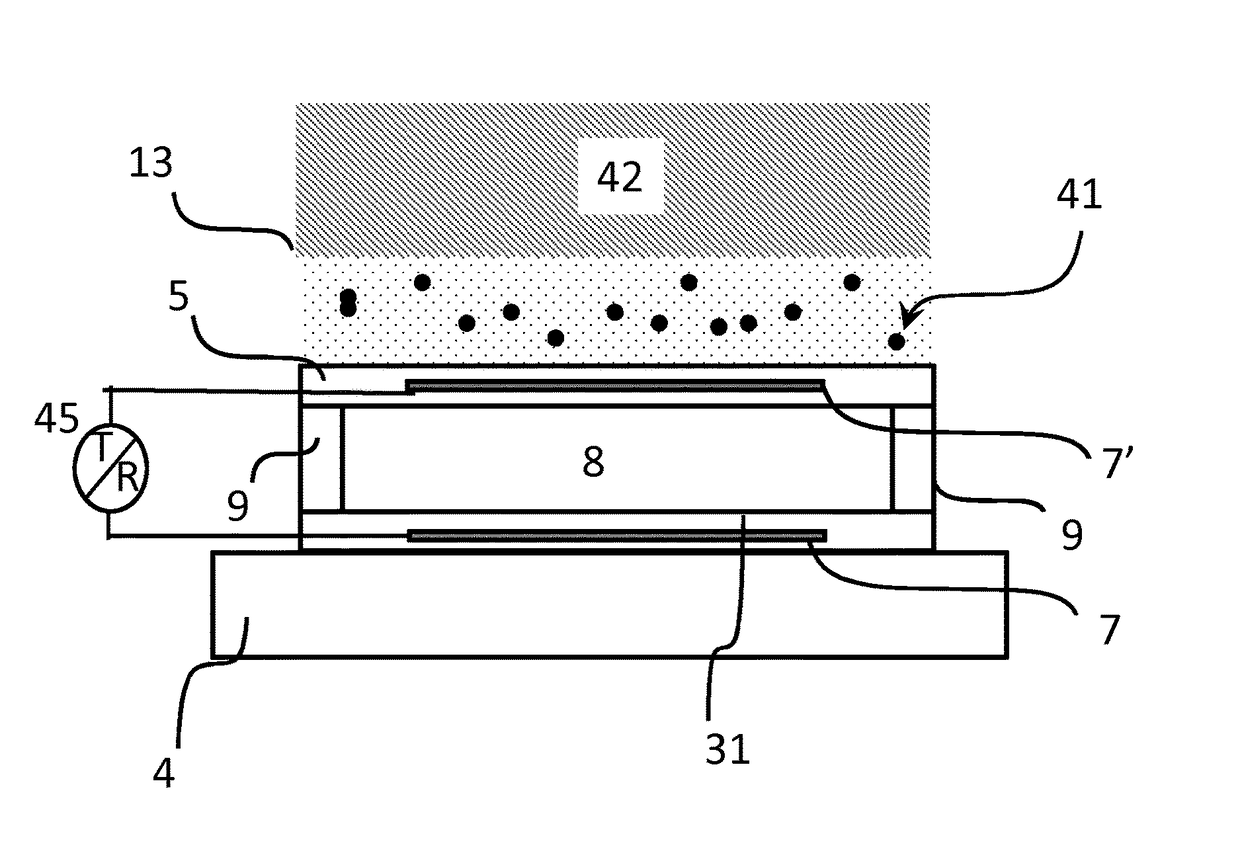
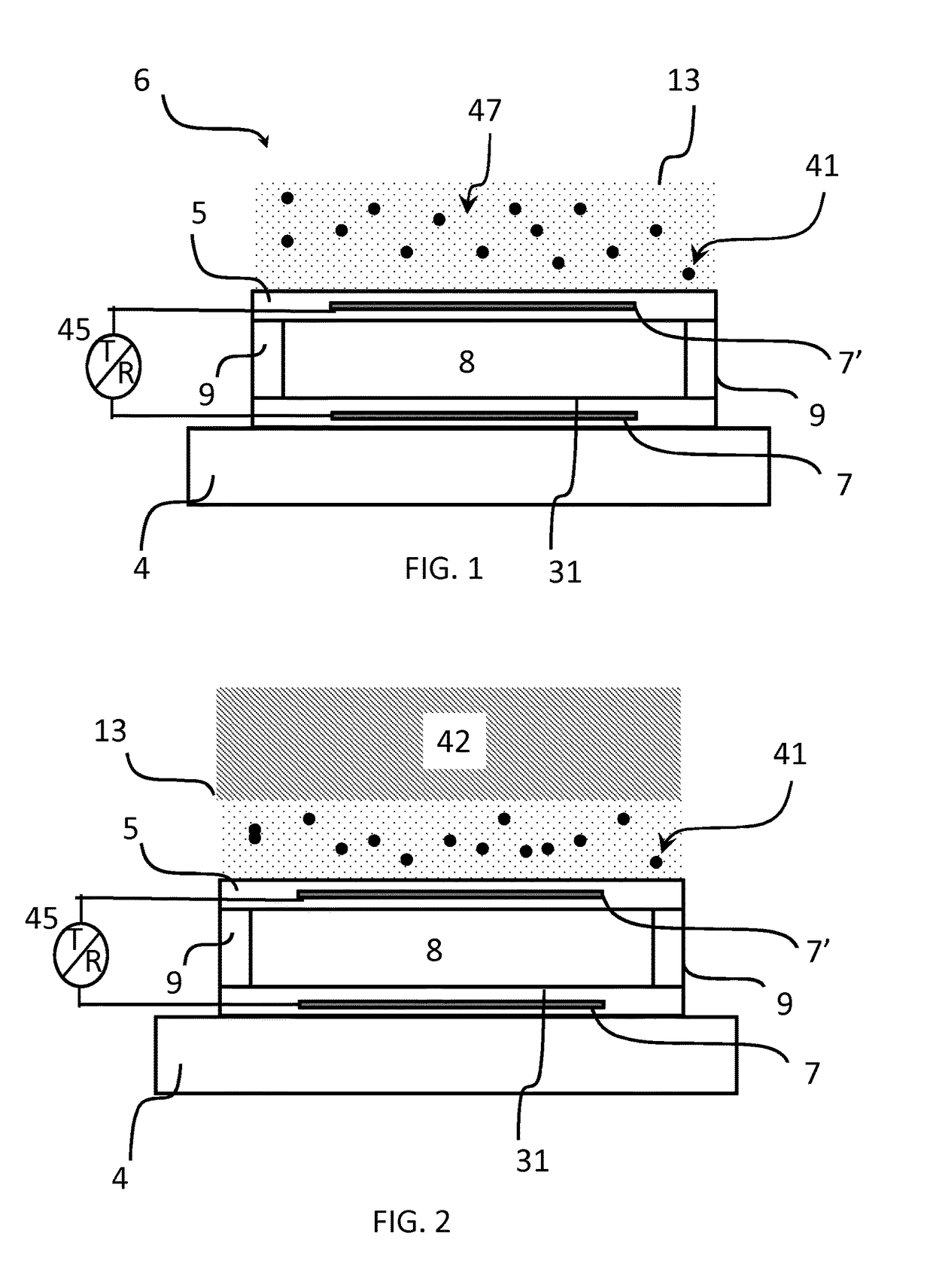
[0052]FIG. 1 shows schematically and exemplarily a CMUT cell in cross section according to the present invention. Such CMUT cell is typically fabricated on a substrate 4, such as a silicon wafer. An ultrasound array of an ultrasound system may comprise one or more CMUT cells 6. The CMUT cells may be either individually activated or in combination with each other. The individual cells can have round, rectangular, hexagon or other peripheral shapes.

[0053]Each CMUT cell has at least a pair of electrodes 7′ and 7 separated by a cavity 8. The cavity 8 is formed in between a membrane 5 that is suspended over a cell floor 31 formed by the top surface of the substrate 4. The membrane 5 may be made of silicon nitride and is adapted to move or vibrate. It can be suspended over the cell floor 31 (or substrate) through a plurality of supporting portions 9 (in FIG. 1 two supporting portions 9 are shown). The electrodes 7, 7′ are made of electrically conductive material, such as metal. The bottom...


PUM


Abstract

An ultrasound array for acoustic wave transmission comprising at least one capacitive micro-machined ultrasound transducer (CMUT) cell (6), wherein the CMUT cell comprises a substrate (4); a first electrode (7); a cell membrane (5) having a second electrode (7′), which opposes the first electrode and the substrate with a cavity (8) there between, wherein the membrane is arranged to vibrate upon the cell activation; and an acoustic window layer (13), overlaying the cell membrane, and having an inner surface opposing the cell membrane and an outer surface. The acoustic window layer comprises a first layer comprising molecules of antioxidant and a polymeric material (47) with insulating particles (41) embedded therein, wherein the polymeric material consists of hydrogen and carbon atoms and has a density equal or below 0.95 g / cm3 and an acoustic impedance equal or above 1.45 MRayl. This acoustic window layer provides an improved acoustic performance, such as wide bandwidth and low attenuation, in application with the CMUT based array.

Description

FIELD OF THE INVENTION[0001]The invention relates to an ultrasound array for acoustic wave transmission comprising at least one capacitive micro-machined ultrasound transducer (CMUT) cell, wherein the CMUT cell comprises a substrate having a first electrode; a cell membrane having a second electrode, which opposes the first electrode with a cavity there between, wherein the membrane is arranged to vibrate upon the cell activation; and an acoustic window layer, overlaying the cell membrane, and having an inner surface opposing the cell membrane and an outer surface.[0002]The invention further relates to a manufacturing method of such an array; and an ultrasonic imaging system comprising such an ultrasound array.BACKGROUND OF THE INVENTION[0003]Central to any ultrasound (imaging) array is the ultrasound transducer which converts electrical energy in acoustic energy and back. Recent progress in semiconductor technology resulted in the development of capacitive micro-machined ultrasound...

Claims


Application Information

Patent Timeline
Patent Type & Authority Applications(United States)
IPC IPC(8): B06B1/02G01S15/02G01S7/521
CPCB06B1/0292G01S15/02G01S7/521
Inventor BECKERS, LUCAS JOHANNES ANNA MARIAHAKKENS, FRANCISCUS JOHANNES GERARDUSDIRKSEN, PETER
Owner KONINKLJIJKE PHILIPS NV
Why Eureka
Try Eureka