
Vessel

Active Publication Date: 2018-03-01
YAMAHA MOTOR CO LTD
View PDF1 Cites 0 Cited by
  • Summary
  • Abstract
  • Description
  • Claims
  • Application Information

AI Technical Summary

Benefits of technology

This patent describes a way to prevent the temperature of air that enters an engine from being increased, which can cause damage and reduce output. This is achieved by using a duct that allows air to flow directly from outside the engine to the air intake port, without being exposed to the hot air generated by the engine. This results in a cooler intake air temperature, which can lead to a larger propulsive force and better engine performance.

Problems solved by technology

However, the inboard space is filled with hot air generated by the engine.
Therefore, there is a concern that the temperature of the intake air of the engine will increase and, correspondingly, the output of the engine will decrease.

Method used


Image

  • Vessel
  • Vessel
  • Vessel

Examples


first preferred embodiment

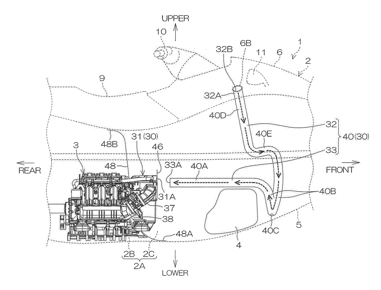
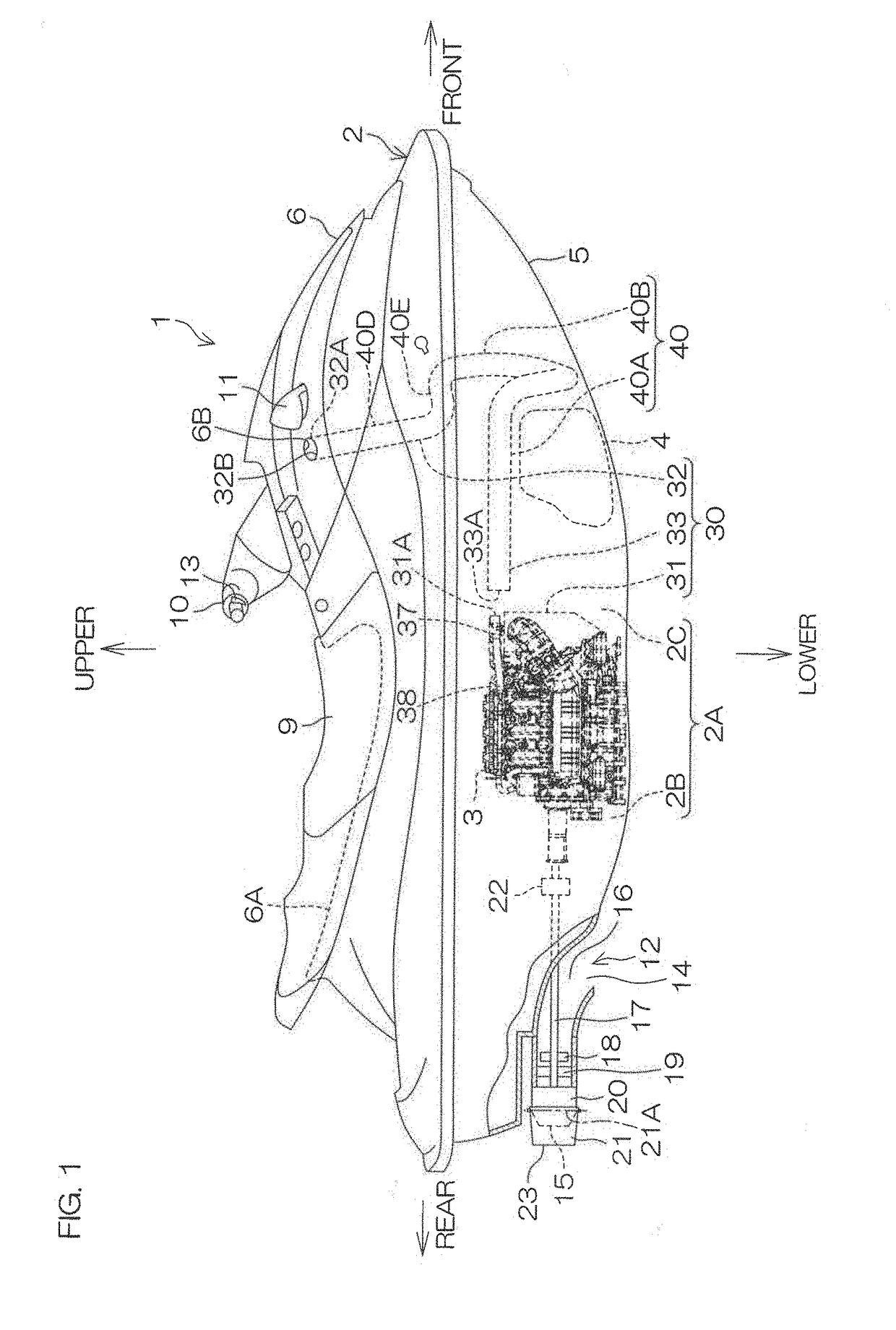
[0046]FIG. 1 is a schematic view of a vessel 1 according to a preferred embodiment of the present invention. A left-right direction in FIG. 1 is a front-rear direction of the vessel 1. A right side in FIG. 1 is a front side of the vessel 1. In the following description, the left-right direction of the vessel 1 is defined based on when looking toward the front side of the vessel 1. In other words, a near side in the direction perpendicular to the sheet of FIG. 1 is the right side of the vessel 1, whereas a far side in the direction perpendicular to the sheet of FIG. 1 is the left side of the vessel 1.

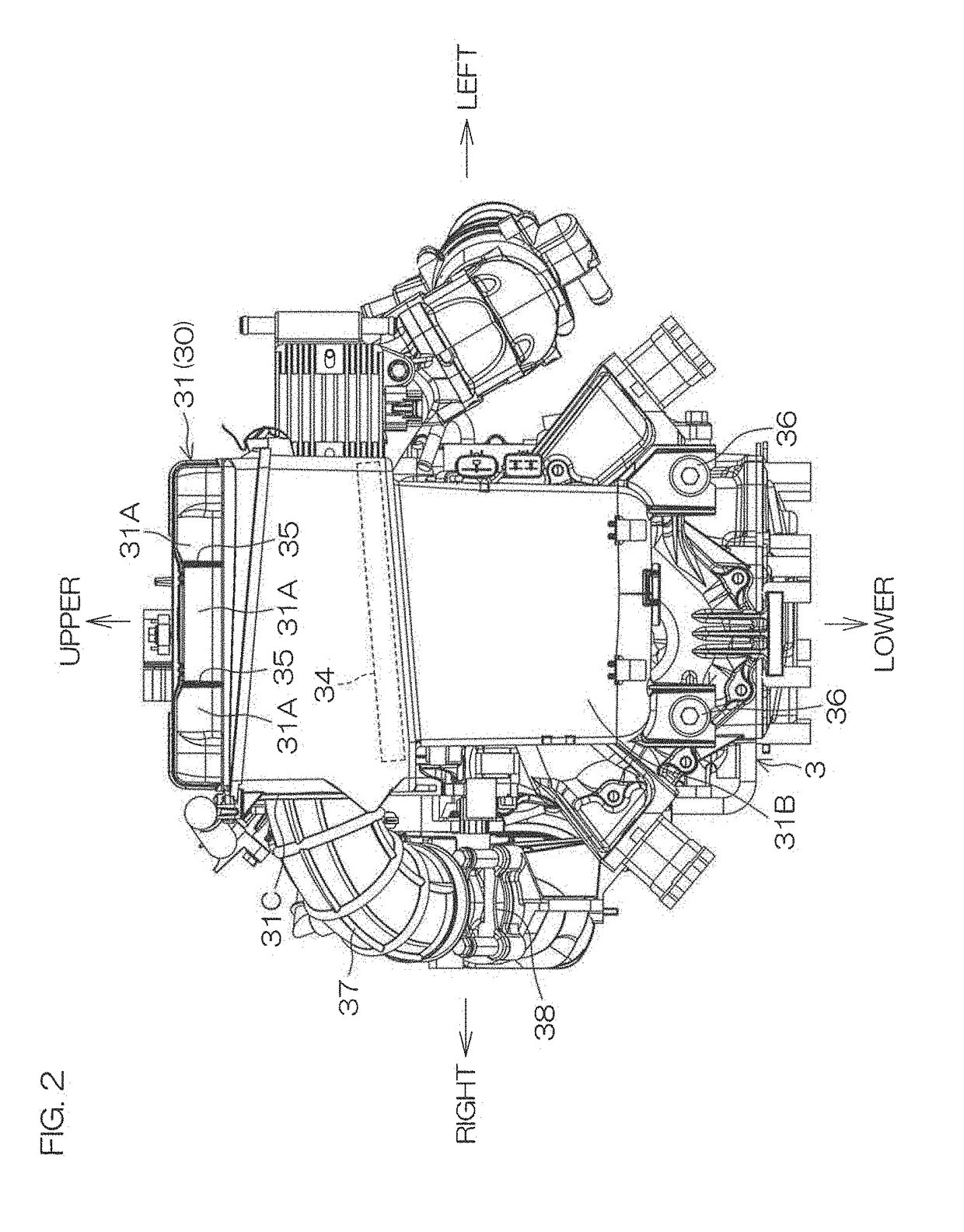
[0047]The vessel 1 includes a vessel body 2, an engine 3, and a fuel tank 4 both of which are contained in the vessel body 2. The vessel body 2 includes a hull 5 defining a vessel bottom and a deck 6 disposed above the hull 5, and extends in the front-rear direction. An internal space 2A is defined inside the vessel body 2. The internal space 2A is defined by the hull 5 and the deck 6 so...


PUM


Abstract

A vessel includes a vessel body, an engine contained in the vessel body, an air intake box including an air intake port and that is attached to the engine, an air intake duct drawn around in the vessel body, and a guide duct including an opening that opposes the air intake port. The air intake box supplies air taken in from the air intake port to the engine. The air intake duct includes an outer end connected to a deck of the vessel body. The guide duct guides air taken in from outside the vessel body by the air intake duct to the opening.

Description

BACKGROUND OF THE INVENTION1. Field of the Invention[0001]The present invention relates to a vessel including an engine.2. Description of the Related Art[0002]A small-sized vessel disclosed in Japanese Patent Application Publication No. 2009-220637 includes a vessel body having an inboard space in its inside and a jet pump disposed behind the vessel body. The inboard space contains an engine that drives the jet pump, a fuel tank for the engine, and an air intake duct through which air passes between the inboard space and outside the vessel body. The engine is disposed in front of the jet pump, and the fuel tank is disposed in front of the engine. The air intake duct has its outer end attached to a wall surface of the vessel body and its inner end disposed in the inboard space. The outer end of the air intake duct includes an air intake port that opens outwardly from the vessel body. Air outside the vessel body passes through the air intake duct from the air intake port, and flows in...

Claims


Application Information

Patent Timeline
IPC IPC(8): F02M35/10B63H11/04F04F5/24
CPCF02M35/10268B63H11/04B63B2751/00F02M35/10124B63B2758/00F04F5/24
Inventor ANMA, HIROFUMIOTSUKA, KENICHISUZUKI, SATORU
Owner YAMAHA MOTOR CO LTD
Learn More