
Contactless charging system, charging station, and contactless charged vehicle

a charging system and charging station technology, applied in the direction of transportation and packaging, instruments, roads, etc., can solve the problems of inability to externally confirm whether the vehicle is charged, difficult to alert the driver of the normal vehicle, and inability to use the contactless power transmission device provided in the parking spa

Active Publication Date: 2018-03-01
TOYOTA JIDOSHA KK
View PDF6 Cites 7 Cited by
  • Summary
  • Abstract
  • Description
  • Claims
  • Application Information

AI Technical Summary

Benefits of technology

The present patent is about a contactless charging system for electric vehicles that efficiently uses parking spaces where a contactless power transmission device is installed. The system includes a management device that controls a restriction device, which allows or restricts the entry of different vehicles into the charging station or parking space. This allows the contactless charged vehicle to be accommodated in a dedicated parking space while also allowing other vehicles to use the available spaces. The management device receives data on the parking use rate and predicts if a future possibility of using the space is low, such as driving a normal vehicle. In this case, the restriction device is switched to the second state, allowing both the contactless charged vehicle and normal vehicles to enter the parking space. This further improves the efficiency of the charging system. Additionally, the contactless charged vehicle can cancel the restriction device to allow for proper parking in the selected space. Overall, this system optimizes the use of available parking spaces and increases the overall efficiency of contactless charging.

Problems solved by technology

Thus, it is concerned that the parking spaces in the charging station are occupied by the normal vehicles, and consequently, the contactless power transmission devices provided in the parking spaces cannot be used for the contactless charged vehicles.
In addition, differing from contact charging with a cable, it is impossible to externally confirm whether the vehicle is charged in the contactless charging.
Thus, it is difficult to alert a driver of the normal vehicle that is not charged to move the normal vehicle.

Method used


Image

  • Contactless charging system, charging station, and contactless charged vehicle
  • Contactless charging system, charging station, and contactless charged vehicle
  • Contactless charging system, charging station, and contactless charged vehicle

Examples


first embodiment

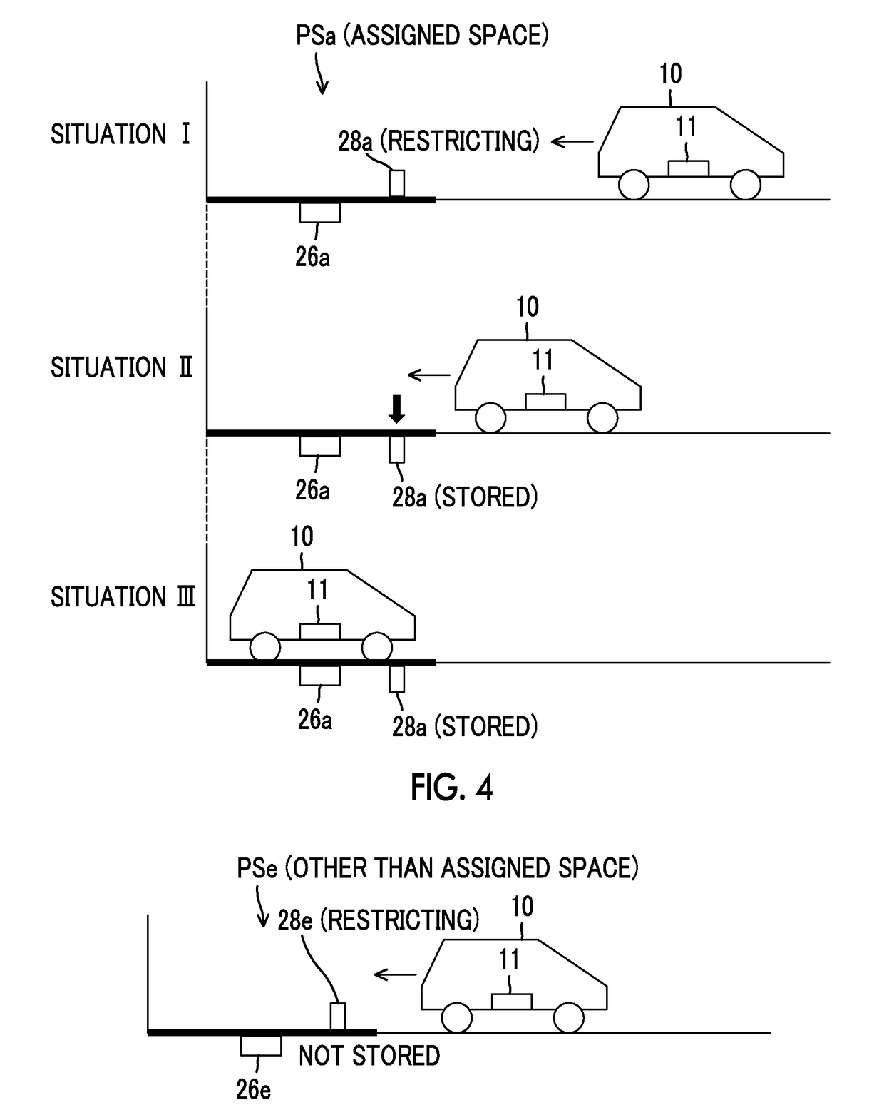
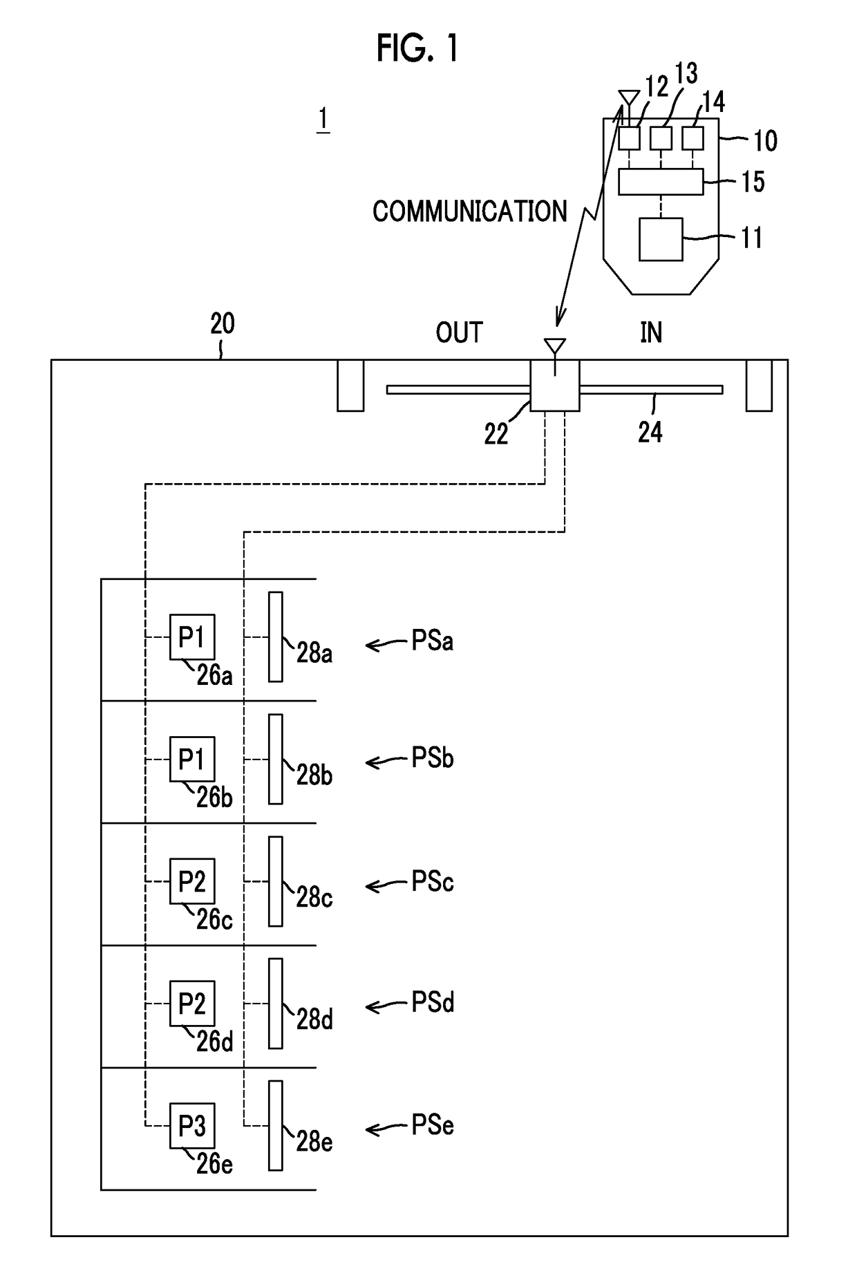
[0023]FIG. 1 is a schematic view of an overall configuration of a contactless charging system 1 according to a The contactless charging system 1 includes a contactless charged vehicle 10 and a charging station 20. The contactless charged vehicle 10 includes a power receiving device 11, a communication device 12, a navigation device 13, a human-machine interface (HMI) device 14, and a controller 15. The charging station 20 includes a management device 22, an entrance gate 24, and a plurality of (five in an example shown in FIG. 1) parking spaces PSa to PSe. The parking spaces PSa to PSe are respectively provided with power transmission devices 26a to 26e and entry prevention plates 28a to 28e. Each of the entry prevention plates 28a to 28e is one example of a restriction device.

[0024]The contactless charged vehicle 10 is an electric vehicle (a hybrid vehicle, an electric automobile, or the like) on which a drive motor and a drive battery (neither of them is shown) are mounted. The c...

second embodiment

[0090]As it has been described so far, the charging station 20A (the management device 22A) according to this second embodiment computes the predicted value of the parking use rate in accordance with the peripheral information obtained from the cloud server 30. When the predicted value of the parking use rate is lower than the threshold, the charging station 20A brings the entry prevention plate of the empty space into the stored state. In this way, when it is predicted that the possibility of the empty space being used by the contactless charged vehicle in the future is low, in addition to the contactless charged vehicle 10, the normal vehicle can also use the parking space. As a result, the parking space in the charging station can further efficiently be used.

[0091]In addition, the above-described embodiments and the modified example thereof can appropriately be combined within the scope that technical contradictions do not occur.


PUM


Abstract

A contactless charging system includes a target vehicle and a charging station. The charging station includes a power transmission device, at least one parking space, a restriction device, and a management device. The management device is configured to control the restriction device to be a second state in which the target vehicle is permitted to enter the charging station and the parking space when the target vehicle is the contactless charged vehicle, and to be a first state in which the target vehicle is restricted to enter the charging station or the parking space when the target vehicle is not the contactless charged vehicle.

Description

CROSS-REFERENCE TO RELATED APPLICATIONS[0001]This application claims priority to Japanese Patent Application No. 2016-164741 filed on Aug. 25, 2016, which is incorporated herein by reference in its entirety including the specification, drawings and abstract.BACKGROUND1. Field[0002]The present disclosure relates to a contactless charging system, a charging station, and a contactless charged vehicle.2. Description of Related Art[0003]In Japanese Patent Application Publication No. 2013-225969 (JP 2013-225969 A), a contactless charging system (a power transmission system) is disclosed. The contactless charging system includes: an electric vehicle that can receive power to charge an in-vehicle battery from outside of the vehicle without contact (hereinafter also referred to as a “contactless charged vehicle”); and a charging station that has a power transmission device capable of transmitting the power to the contactless charged vehicle without contact (hereinafter also referred to as a ...

Claims


Application Information

Patent Timeline
Patent Type & Authority Applications(United States)
IPC IPC(8): E04H6/42B60L11/18E01F13/04
CPCE04H6/42B60L11/182B60L11/1846E01F13/046E01F13/042B60L2230/16B60L11/1824H02J50/10B60L53/30B60L53/38Y02T10/7072Y02T90/14B60L53/12B60L53/65B60L53/305Y02T10/70Y02T90/12Y02T90/16B60L53/36B60Y2200/91B60Y2200/92G06Q50/40
Inventor KATANODA, TOMOYA
Owner TOYOTA JIDOSHA KK
Learn More