
Aircraft tail with cross-flow fan systems

a technology of cross-flow fan and tail, which is applied in the direction of machines/engines, liquid fuel engines, transportation and packaging, etc., can solve the problems of unacceptably high noise produced by traditional tail rotors, flying over acoustic problems, and being susceptible to striking people or other objects

Active Publication Date: 2018-02-15
BELL HELICOPTER TEXTRON INC
View PDF15 Cites 3 Cited by
  • Summary
  • Abstract
  • Description
  • Claims
  • Application Information

AI Technical Summary

Benefits of technology

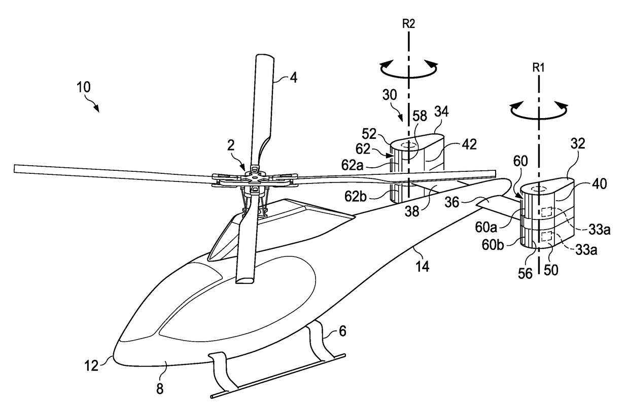
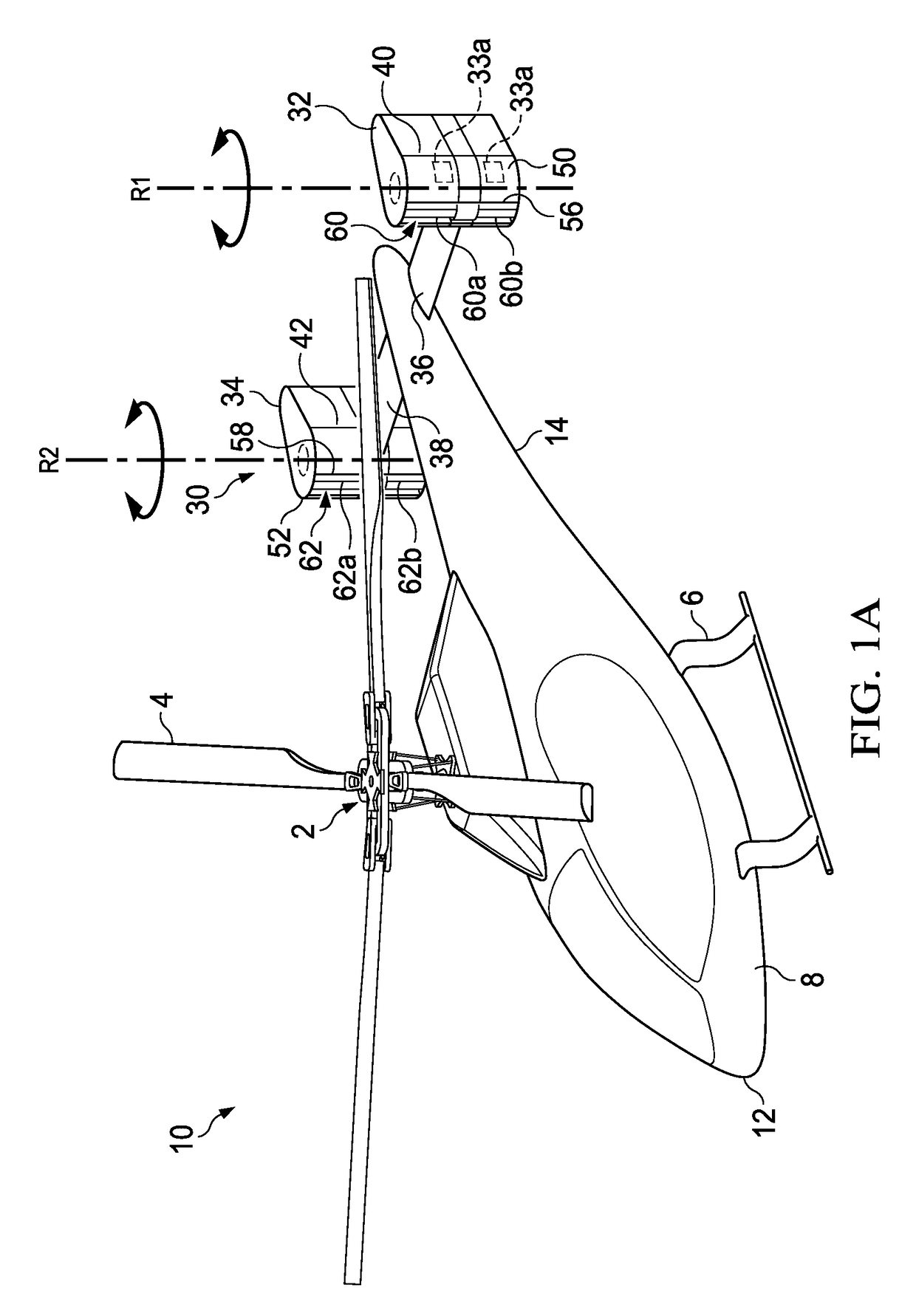
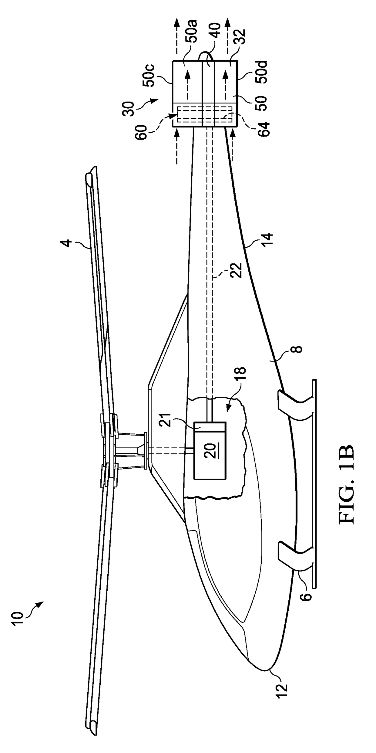
The patent describes an aircraft with a cross-flow fan system that can provide a forward thrust vector, an anti-torque vector, or an anti-torque vector. The fan system can be retrofitted onto an existing aircraft and includes a variable thrust cross-flow fan assembly and a control assembly to change the pitch angle configuration of the blades. The cross-flow fan system can be connected to the drive system of the aircraft and can be mounted to the tail portion of the aircraft. The technical effects of the patent include improved performance and efficiency of the aircraft's fan system.

Problems solved by technology

First, because the tail rotor blades are large and openly exposed, they are susceptible to striking people or other objects while in operation.
Second, the noise produced by traditional tail rotors can be unacceptably high, creating flyover acoustic problems.
Such noise may be undesirable in a low noise environment or during clandestine activities.
Traditional tail rotors may also create undesirable profile drag during flight, and / or cause thrust reduction during sideward flight.

Method used


Image

  • Aircraft tail with cross-flow fan systems
  • Aircraft tail with cross-flow fan systems
  • Aircraft tail with cross-flow fan systems

Examples


Embodiment Construction

[0043]Illustrative embodiments of the apparatus and method are described below. In the interest of clarity, all features of an actual implementation may not be described in this specification. It will of course be appreciated that in the development of any such actual embodiment, numerous implementation-specific decisions must be made to achieve the developer's specific goals, such as compliance with system-related and business-related constraints, which will vary from one implementation to another. Moreover, it will be appreciated that such a development effort might be complex and time-consuming but would nevertheless be a routine undertaking for those of ordinary skill in the art having the benefit of this disclosure.

[0044]In the specification, reference may be made to the spatial relationships between various components and to the spatial orientation of various aspects of components as the devices are depicted in the attached drawings. However, as will be recognized by those ski...


PUM


Abstract

In one aspect, there is provided an aircraft, including a fuselage having a longitudinal axis extending from a front portion through an aft portion; first and second tail members extending from the aft portion; a first cross-flow fan system rotatably mounted to the first tail member; and a second cross-flow fan system rotatably mounted to the second tail member. The first and second cross-flow fan systems are configured to provide a forward thrust vector and an anti-torque vector on the aircraft. The first and second cross-flow fan systems can have a rotational axis oriented generally vertically. In another aspect, there is an aircraft including a fuselage having a front portion and a tail portion; and a cross-flow fan system supported by the tail portion. Embodiments include a cross-flow fan system retrofittable onto an aircraft and methods for retrofitting an aircraft with a cross-flow fan system.

Description

CROSS-REFERENCE TO RELATED APPLICATIONS[0001]This application claims priority as a continuation of U.S. patent application Ser. No. 15 / 233,897, filed Aug. 10, 2016, and U.S. patent application Ser. No. 15 / 252,916 filed Aug. 31, 2016. Each patent application identified above is incorporated herein by reference in its entirety.BACKGROUNDTechnical Field:[0002]The present disclosure relates, in general, to an aircraft tail with cross-flow fan systems and, in particular, to cross-flow fan systems supported by a tail section of an aircraft.Description of Related Art:[0003]The main rotor of a helicopter, which produces lift necessary for flight, also produces a counteracting torque force on the fuselage of the helicopter. The helicopter's tail rotor, located to the rear of the main rotor, is used to counteract this torque and to control the yaw of the helicopter. Tail rotors are typically mounted on a horizontal axis perpendicular to the direction of flight of the aircraft. The blades of a...

Claims


Application Information

Patent Timeline
Patent Type & Authority Applications(United States)
IPC IPC(8): B64C27/82B64C27/06F04D17/04F04D29/42F04D25/16F04D27/00
CPCB64C27/82F04D17/04F04D29/4226F04D27/002B64C2027/8227F04D25/166B64C27/06B64C5/02B64C9/00B64C39/006B64C11/006B64C23/02B64C2027/8218B64C2027/8254
Inventor GRONINGA, KIRK L.ROBERTSON, DANIEL B.LOUIS, MATTHEW E.
Owner BELL HELICOPTER TEXTRON INC
Learn More