Hermetic Food Container
- Summary
- Abstract
- Description
- Claims
- Application Information
AI Technical Summary
Benefits of technology
Problems solved by technology
Method used
Image
Examples
first embodiment
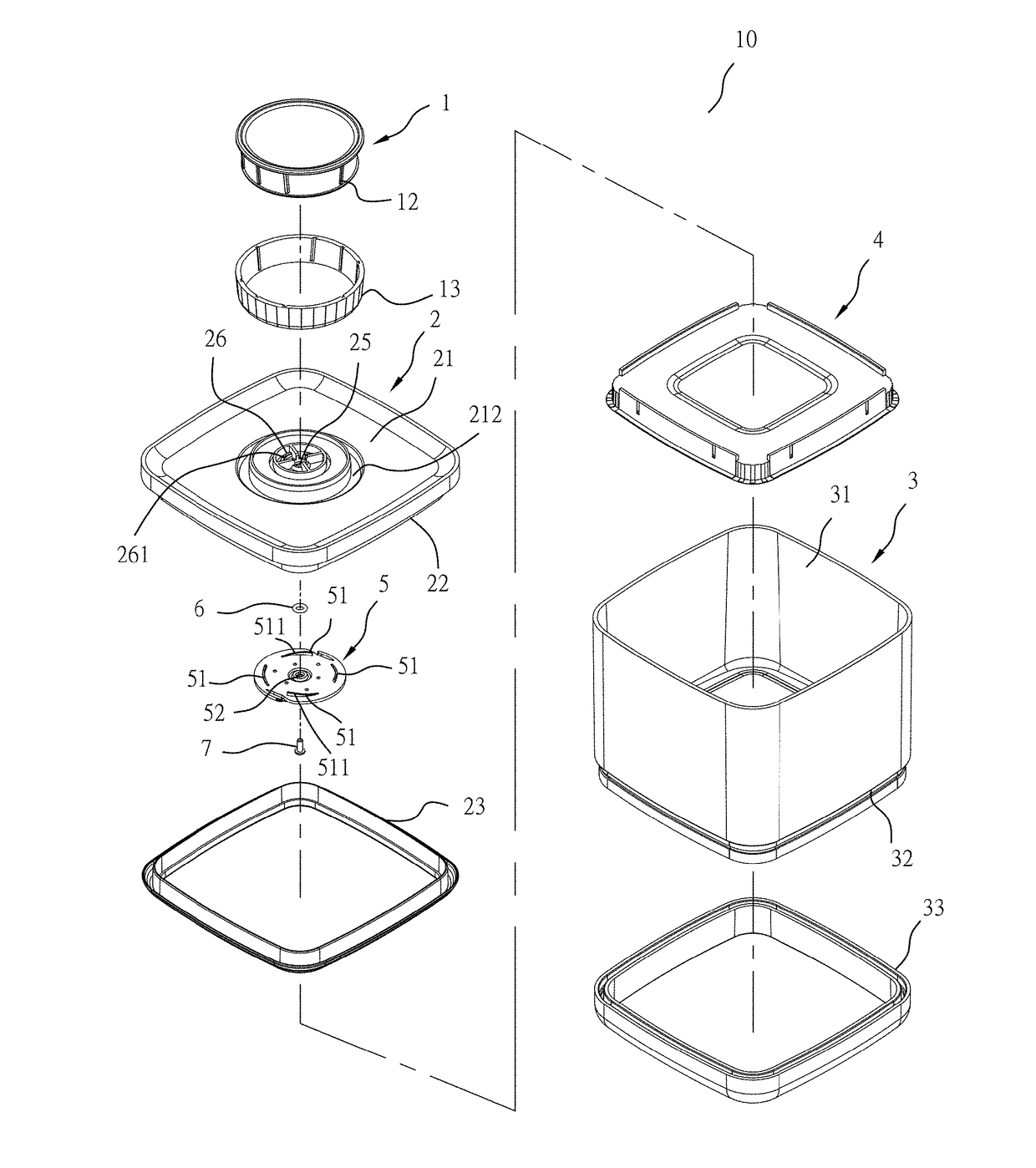
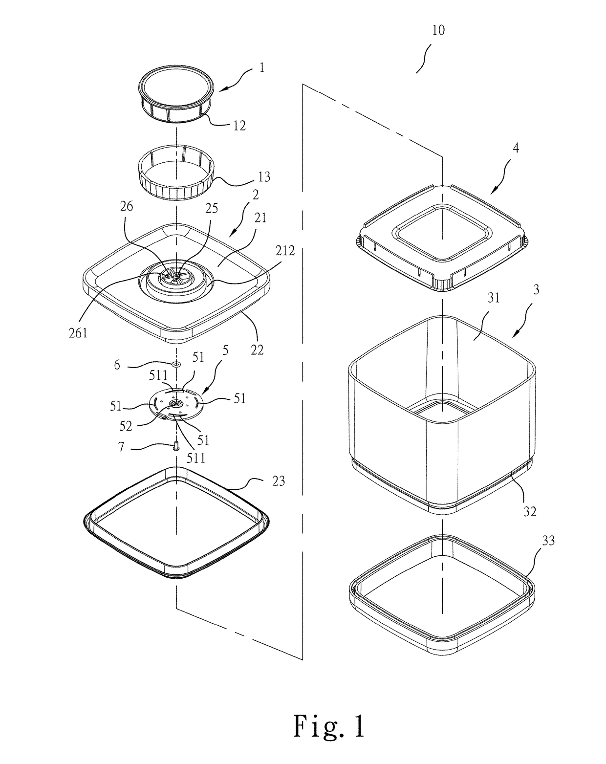
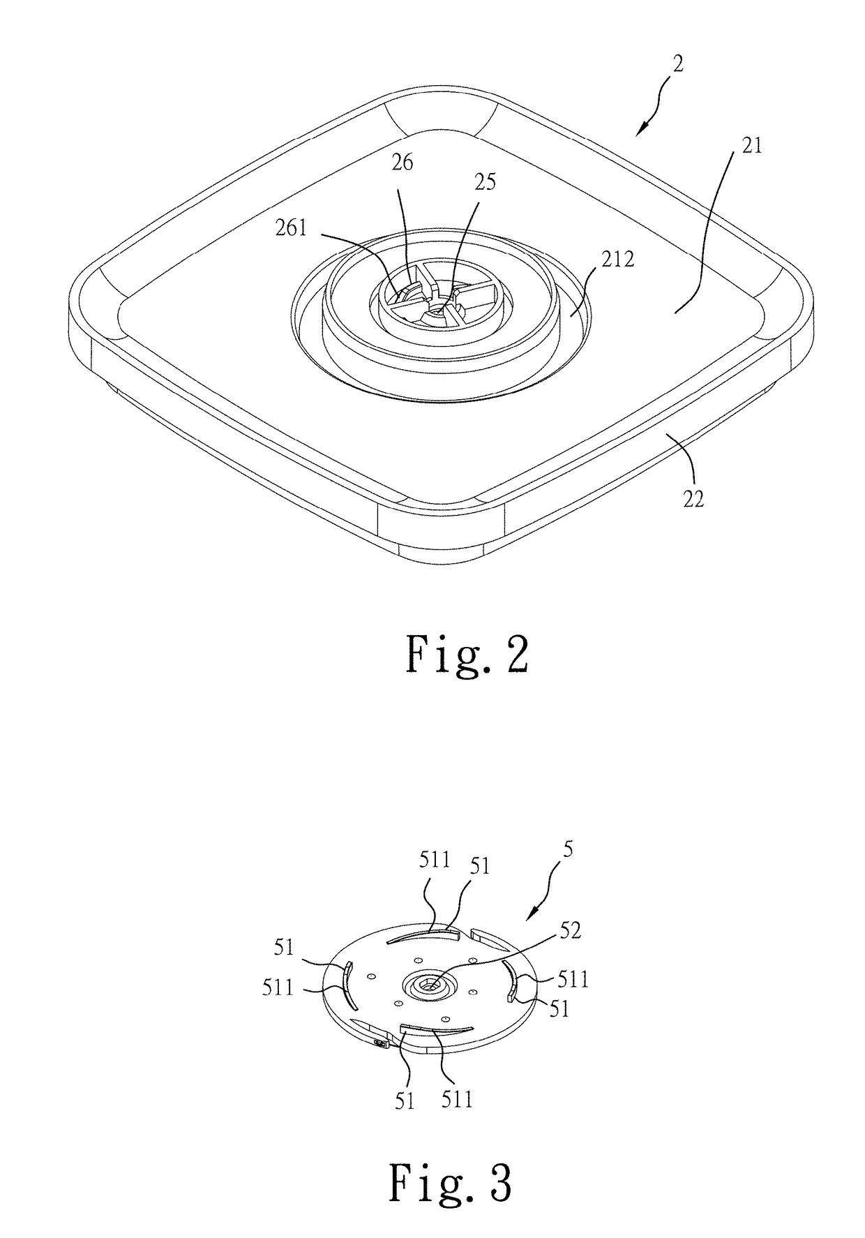
[0035]Based on the aforesaid structural composition of the hermetic food container 10 in accordance with the present invention, when the rotary knob 1 is rotated in the first direction, i.e., clockwise direction, the rotary knob 1 is moved upward relative to the top cover 2 (see FIG. 10) subject to the guidance of the guiding surface 261 of each lift guiding block 26 at the face panel 21 of the top cover 2, causing the gasket ring 6 to be lifted with the bottom stem 11 of the rotary knob 1 into abutment against the inner peripheral wall 251 of the coupling hole 25 of the top cover 2 (see FIG. 10), and thus, the expected sealing effect is achieved. On the contrary, when the rotary knob 1 is rotated in the second direction, i.e., counter-clockwise direction, the rotary knob 1 is moved downward relative to the top cover 2 (see FIG. 10) subject to the guidance of the guiding surface 511 of each guide block 51 of the guide seat 5, causing creation of a gap 27 between the gasket ring 6 an...
second embodiment
[0045]Based on the aforesaid structural composition of the hermetic food container 10 in accordance with the present invention, when the rotary knob 1 is rotated in the first direction, i.e., clockwise direction, the rotary knob 1 is moved upward relative to the top cover 2 (see FIG. 15) subject to the guidance of the guiding surface 261 of each lift guiding block 26 at the face panel 21 of the top cover 2, causing the gasket ring 6′ to be stopped by the bottom edge 121 of the annular peripheral wall 12 of the rotary knob 1 (see FIG. 15), and thus, the expected sealing effect is achieved. On the contrary, when the rotary knob 1 is rotated in the second direction, i.e., counter-clockwise direction, the rotary knob 1 is moved downward relative to the top cover 2 subject to the guidance of the guiding surface 511 of each guide block 51 of the guide seat 5, causing creation of a gap 28 between the gasket ring 6′ and the bottom edge 121 of the annular peripheral wall 12 of the rotary kno...
third embodiment
[0054]Based on the aforesaid structural composition of the hermetic food container 10 in accordance with the present invention, when the rotary knob 1 is rotated in the first direction, i.e., clockwise direction, the at least one lifting guide block 531 of the guide seat 5 is guided by the respective at least one lifting guide groove 29 of the face panel 21 of the top cover to move upward, and thus, the rotary knob 1 is moved with the guide seat 5 upwardly relative to the top cover 2 (see FIG. 20), forcing the gasket ring 6 at the bottom stem 11 of the rotary knob 1 to abut against an inner peripheral wall 251 of the coupling hole 25 of the top cover 2 (see FIG. 20), and thus, the expected sealing effect is achieved. On the contrary, when the rotary knob 1 is rotated in the second direction, i.e., counter-clockwise direction, the at least one lifting guide block 531 of the guide seat 5 is guided by the respective at least one lifting guide groove 29 of the face panel 21 of the top c...
PUM
 Abstract
Description
Claims
Application Information
 - R&D
- Intellectual Property
- Life Sciences
- Materials
- Tech Scout
- Unparalleled Data Quality
- Higher Quality Content
- 60% Fewer Hallucinations
Browse by: Latest US Patents, China's latest patents, Technical Efficacy Thesaurus, Application Domain, Technology Topic, Popular Technical Reports.
© 2025 PatSnap. All rights reserved.Legal|Privacy policy|Modern Slavery Act Transparency Statement|Sitemap|About US| Contact US: help@patsnap.com


