Dispenser with metal sheet outer surface, support structure, metal sheet and manufacturing method

a technology of metal sheets and dispensers, applied in the field of dispensers, can solve the problems of difficult cleaning and disinfection of plastic dispensers, low quality of metal dispensers, and low manufacturing cost of metal dispensers, so as to avoid interference, improve visual appearance, and increase the cost of the dispenser

Active Publication Date: 2018-01-18
ESSITY HYGIENE & HEALTH AB
View PDF0 Cites 2 Cited by
  • Summary
  • Abstract
  • Description
  • Claims
  • Application Information

AI Technical Summary

Benefits of technology

The patent text describes a dispenser design that prevents the sharp edge of a metal sheet from being exposed and potentially coming into contact with a person. This is achieved by using a rim on the edge of the metal sheet that is located within a groove of a plastic support structure. The design also enhances the visual appearance of the outer surface of the dispenser by concealing the sharp metal edges. The metal sheet used in the dispenser has a thickness of 0.2-1.5 millimetres, specifically in the range of 0.3-0.7 millimetres, to provide stability while minimizing costs.

Problems solved by technology

Dispensers made of injection-moulded plastic material have the benefit of enabling relatively low manufacturing cost, low weight and a large freedom in terms of the design of the dispenser, such as complex three dimensional shaping, but plastic dispensers may be difficult to keep clean and disinfect due to scratches in the outer plastic surface and due to the limited types of cleaning liquid that can be used without damaging the outer plastic surface.
Plastic dispensers are also generally perceived as less robust and of lower quality.
However, metal dispensers have a relatively high manufacturing cost.
However, any exposed edges of the metal sheet may hinder proper use, cleaning or refilling of the dispenser.

Method used


Image

  • Dispenser with metal sheet outer surface, support structure, metal sheet and manufacturing method
  • Dispenser with metal sheet outer surface, support structure, metal sheet and manufacturing method
  • Dispenser with metal sheet outer surface, support structure, metal sheet and manufacturing method

Examples


Embodiment Construction

[0061]Various aspects of the invention will hereinafter be described in conjunction with the appended drawings to illustrate and not to limit the invention, wherein like designations denote like elements, and variations of the inventive aspects are not restricted to the specifically shown embodiments, but are applicable to other variations of the invention. Further, while various features are grouped together in the embodiments for the purpose of streamlining the disclosure, it is appreciated that features from different embodiments may be combined to form additional embodiments that are all contemplated within the scope of the disclosure.

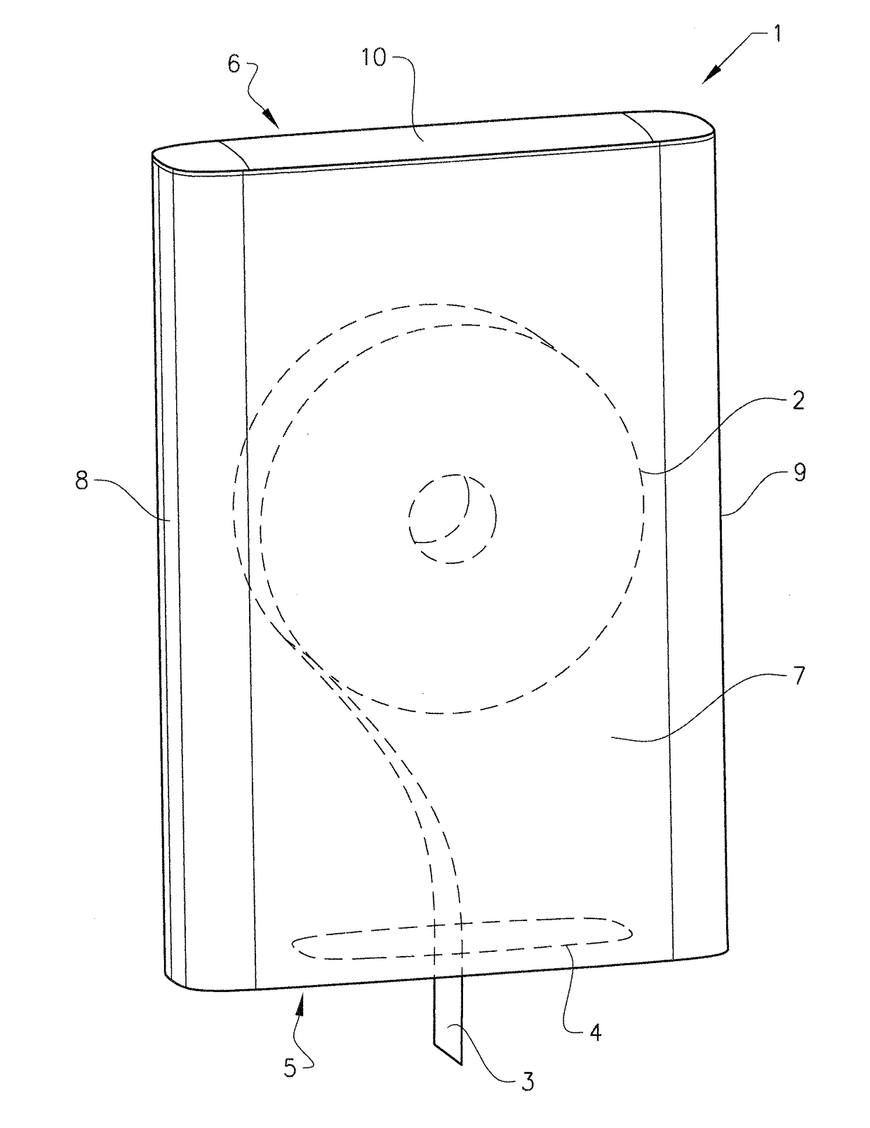
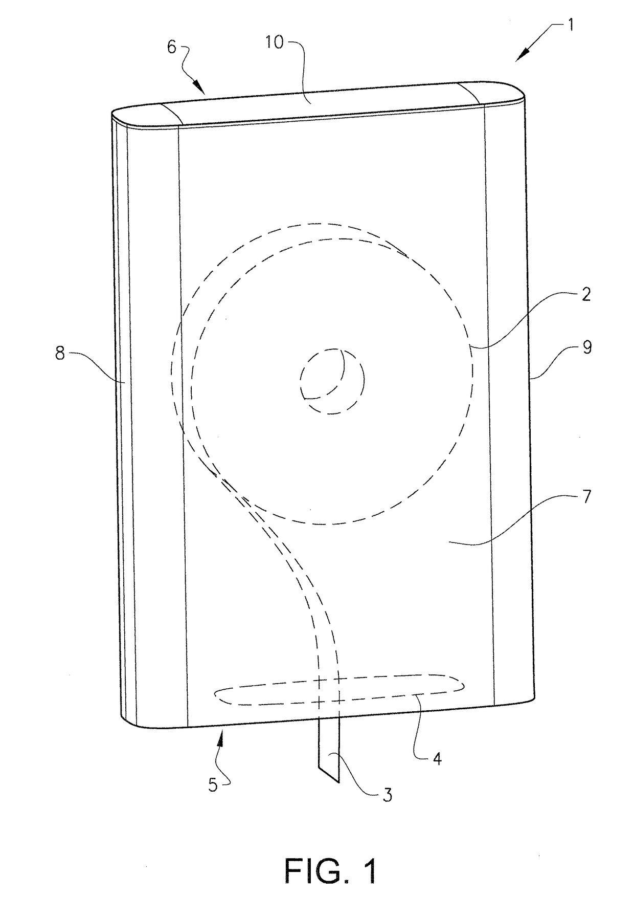
[0062]FIG. 1 illustrates schematically a perspective view of a dispenser 1. The dispenser is schematically depicted in a closed state including a single roll 2 of sheet material having a leading end 3 projecting out of the dispenser 1 through a dispensing hole 4 in a bottom wall 5 of the dispenser 1. The single roll 2 of sheet material is typically...


PUM


Abstract

A dispenser for storing and dispensing a hygiene product, includes at least one wall having a support structure made at least mainly of plastic material, and at least one metal sheet attached on an outer side of the support structure. The at least one metal sheet includes a rim extending along at least a part of a peripheral side edge of the at least one metal sheet and a plurality of fastening tabs distributed around the peripheral side edge of the at least one metal sheet. The support structure includes at least one groove arranged to receive the rim and a plurality of apertures configured to receive the fastening tabs. Also, a method for manufacturing the dispenser, the support structure with groove and apertures as such, and the metal sheet with a rim and fastening tabs as such is disclosed.

Description

CROSS-REFERENCE TO PRIOR APPLICATION[0001]This application is a §371 National Stage Application of PCT International Application No. PCT / SE2015 / 050092 filed Jan. 29, 2015, which is incorporated herein in its entirety.TECHNICAL FIELD[0002]The disclosure relates to dispensers for storing and dispensing hygiene products, as well as associated supporting structures, manufacturing methods, and materials for making such dispensers.[0003]The disclosure can be applied to all types of dispensers for hygiene products, such as absorbent sheet material, wiping material, liquids or foams of soap, alcohol gel, body or hair care products, or similar hygiene products.[0004]Although the invention will be described with respect to a specific type of dispenser, the invention is not restricted to this particular dispenser, but may also be used in other dispensers for hygiene products.BACKGROUND[0005]There is a general desire to provide dispensers having robust designs and aesthetically pleasing appeara...

Claims


Application Information

Patent Timeline
IPC IPC(8): A47K10/32
CPCA47K10/32A47K2010/3233A47K5/12F16B5/0096A47K10/36
Inventor ARLEMARK, MALKUSLANGMAID, MICHAEL N.
Owner ESSITY HYGIENE & HEALTH AB
Why Eureka
Try Eureka