
Occupancy sensing and building control using mobile devices

a technology of occupancy sensing and building control, applied in the field of environmental control systems, can solve the problems of inability to provide timely and accurate counts of the number of occupants at a given time, cost and error, and increase the risk of accidents,

Active Publication Date: 2018-01-04
TRANE INT INC
View PDF18 Cites 54 Cited by
  • Summary
  • Abstract
  • Description
  • Claims
  • Application Information

AI Technical Summary

Benefits of technology

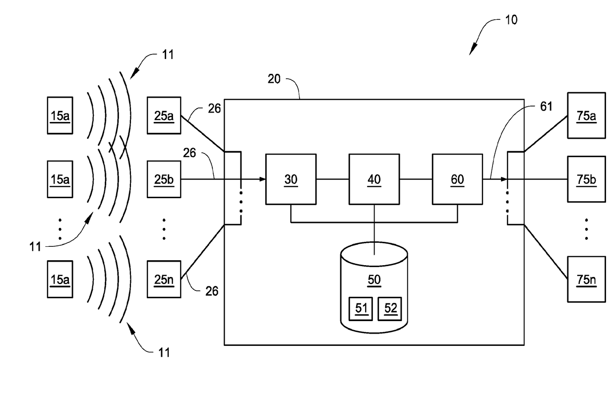
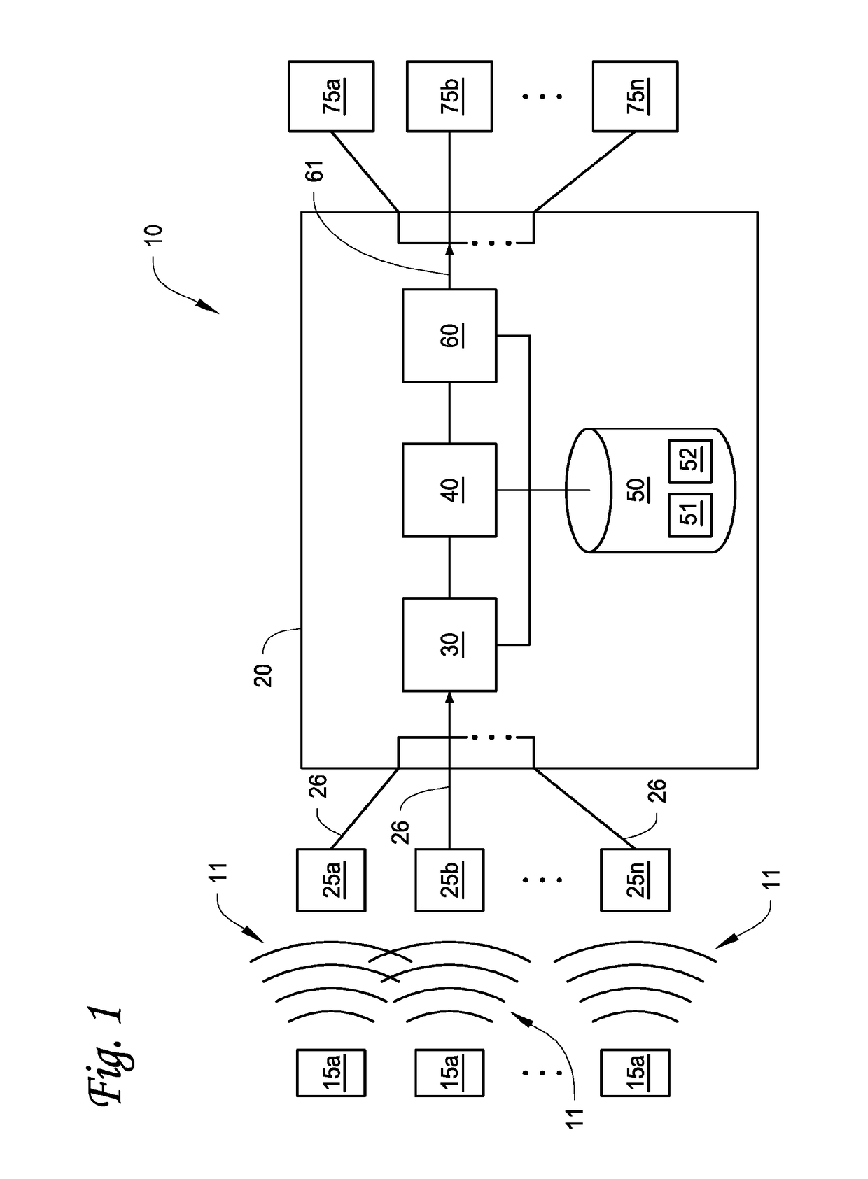
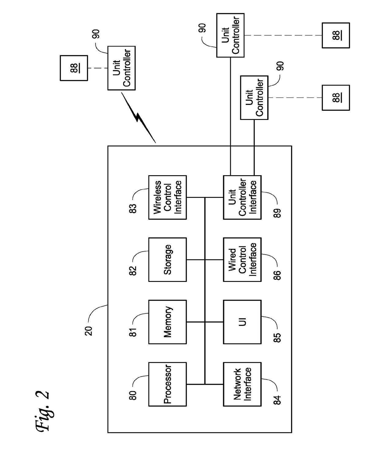
The present patent is about a building control system that uses mobile devices to control various devices in a building. The system includes a controller, communication access points, and a map of the building that identifies different control zones. The controller uses the mobile devices' unique identifier and signal strength to determine their location. The system also includes an occupancy module that determines the number of mobile devices in each control zone and a rules processor that compares the mobile devices' location to pre-defined rules to control the devices in the building. The system can also include a status display that shows the occupancy of each control zone and can alert users when the occupancy reaches a certain level. The technical effect of this patent is to provide a more efficient and effective building control system that uses mobile devices to control various devices in the building.

Problems solved by technology

Known techniques currently in use for occupancy sensing may have drawbacks in that they are often costly to implement and error-prone.
These techniques are unable to provide timely and accurate counts of the number of occupants at a given point in time.
Such inaccuracies give rise to cumulative errors.
Scheduling techniques for HVAC control may have drawbacks, because they do not rely on actual occupancy, but rather they rely on anticipated occupancy to control HVAC functions.

Method used


Image

  • Occupancy sensing and building control using mobile devices
  • Occupancy sensing and building control using mobile devices
  • Occupancy sensing and building control using mobile devices

Examples


Embodiment Construction

[0022]Particular illustrative embodiments of the present disclosure are described hereinbelow with reference to the accompanying drawings, however, the disclosed embodiments are merely examples of the disclosure which may be embodied in various forms. Well-known functions or constructions and repetitive are not described in detail to avoid obscuring the present disclosure in unnecessary or redundant detail. Therefore, specific structural and functional details disclosed herein are not to be interpreted as limiting, but merely as a basis for the claims and as a representative basis for teaching one skilled in the art to variously employ the present disclosure in virtually any appropriately detailed structure. In this description, as well as in the drawings, like-referenced numbers represent elements which may perform the same, similar, or equivalent functions. The word “exemplary” is used herein to mean “serving as an example, instance, or illustration.” Any embodiment described here...


PUM


Abstract

Apparatus, systems and methods for ascertaining the occupancy of a building are presented. The building is divided into one or more control zones which correspond to physical areas of the building associated with controllable modules, such as HVAC units, lighting, irrigation, or other environmental features such as fountains, music, video, and the like. Zone parameters define how zone devices shall react to the number of occupants located in the particular zone. A building control system detects individual mobile devices in and around the building, and determines the locations of each device by using trilateration and / or location services. The identified mobile devices act as proxies for building occupants. The locations of these devices are correlated with the locations of the zones in the building, and the building control system then adjusts the operating parameters of the zone based on the number of devices present in the zone.

Description

BACKGROUND1. Technical Field[0001]The present disclosure relates generally to environmental control systems, such as heating, ventilation, and air conditioning (HVAC) systems and lighting control systems, and in particular, to improved systems and methods for sensing occupants of a building for environmental control purposes.2. Background of Related Art[0002]A heating, ventilation, and air conditioning (HVAC) system generally includes equipment configured to control one or more environmental conditions such as, but not limited to, temperature, humidity, air quality, or the like. An HVAC system is generally equipped with a umber of HVAC components, such as a sensors, variable air volume (VAV) boxes, air handlers, chillers, and so forth, which interact to provide the desired environmental condition within a facility. The function and control of the HVAC equipment is typically adjusted by an HVAC automation and energy management system, which may include equipment controllers, system c...

Claims


Application Information

Patent Timeline
IPC IPC(8): G05B19/048F24F11/00
CPCG05B19/048F24F11/0012F24F11/0034F24F11/006F24F2011/0035F24F2011/0058F24F2011/0063F24F2011/0069G05B2219/2614G05B2219/2642G05B2219/2625H04W4/04G05B15/02F24F11/65F24F11/61F24F2120/10F24F11/62H04W4/38H04W4/33H04W4/021F24F2120/12F24F11/63F24F11/57F24F11/64F24F2130/00F24F2130/10F24F2110/10
Inventor HAINES, PAUL EDMUNDFLETCHER, THOMAS A.KINNEY, BRYANOLSON, JOHN C.
Owner TRANE INT INC
Learn More