
Energy harvesting water vehicle

a water vehicle and energy harvesting technology, applied in waterborne vessels, dynamo-electric machines, floating buildings, etc., can solve the problems of lack of efficiency and size limitations of solar panels, energy dissipation to the environment can be especially great, and the effect of reducing drag

Inactive Publication Date: 2018-01-04
KING ABDULLAH UNIV OF SCI & TECH
View PDF16 Cites 2 Cited by
  • Summary
  • Abstract
  • Description
  • Claims
  • Application Information

AI Technical Summary

Benefits of technology

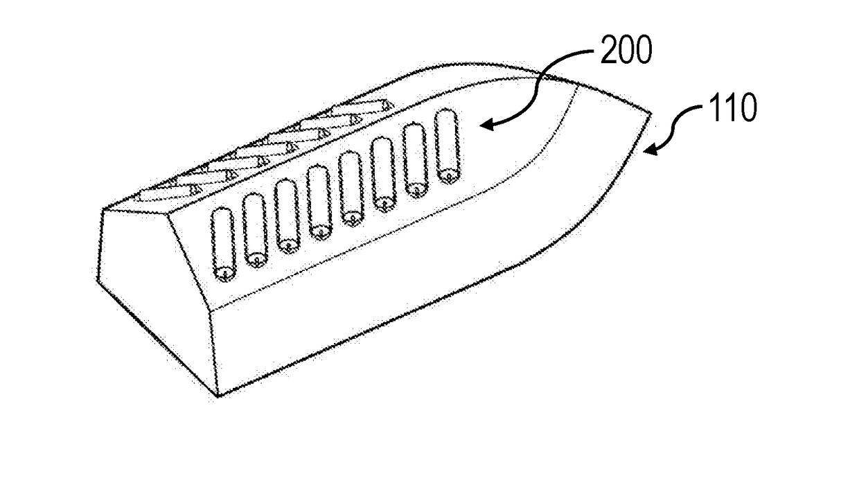
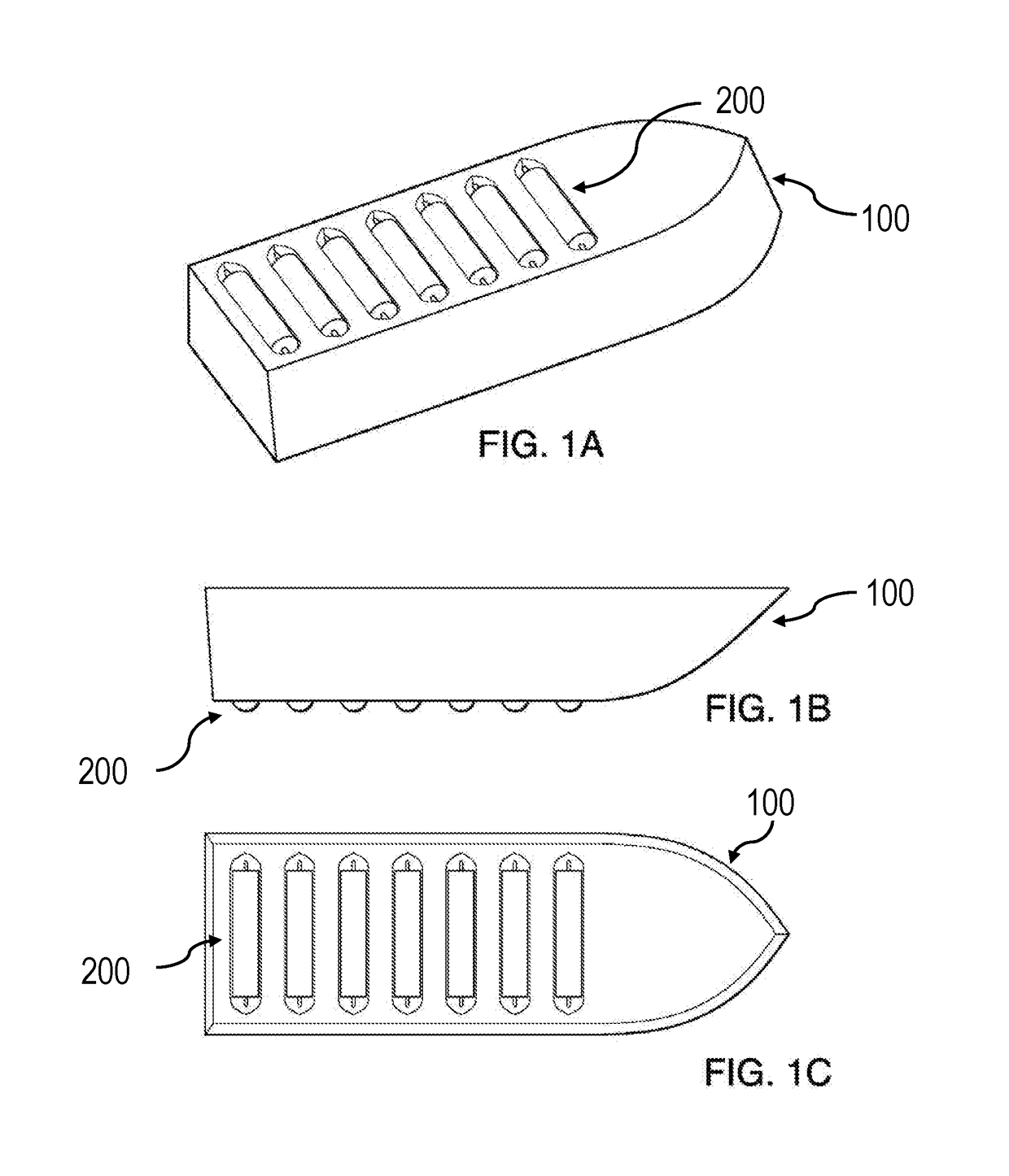
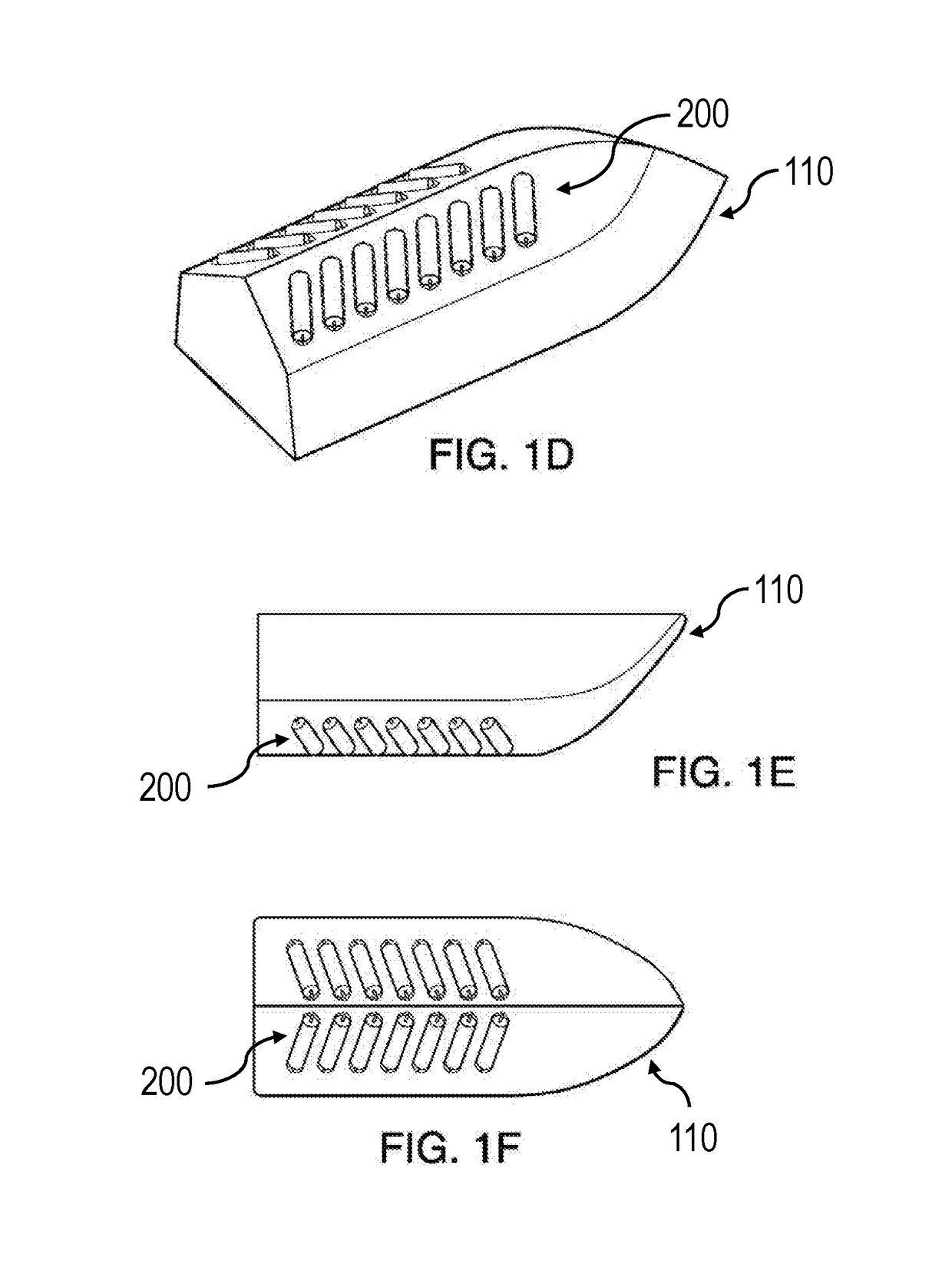
This patent is about an efficient water vehicle that can harvest energy from its movement. The vehicle has a base made up of rotating cylindrical drums that reduce the drag between the vehicle and the water. These drums can be shaped in various ways to increase efficiency. When the vehicle moves, the reduced drag results in increased speed, making the vehicle more efficient in traveling between two points. The mechanical energy of the drums can also be transformed into electrical energy using a device like a dynamo. The invention also includes a second mode that further improves efficiency by reducing the drag at the vehicle-water interface and generating power from the rotational motion of the connected drums.

Problems solved by technology

For water vehicles or watercraft, such as sailboats and powerboats, energy dissipation to the environment can be especially great due to the resistance from the water.
For sailboats, where weight is often an important consideration, electric power can be limited because of the lack of a high energy output motor to drive an alternator, the lack of efficiency and size limitations of solar panels, and the weight and capacity limits of batteries.
For sailboats that do have an onboard generator, it may be necessary to recharge the batteries with it, which causes noise, smoke, and pollution lasting for up to a few hours.
For recreational sailings, the generator's shortcomings can be particularly problematic for the enjoyment of the experience.

Method used


Image

  • Energy harvesting water vehicle
  • Energy harvesting water vehicle
  • Energy harvesting water vehicle

Examples


Embodiment Construction

[0021]In the following detailed description of the preferred embodiments, reference is made to the accompanying drawings, which form a part hereof, and within which are shown by way of illustration specific embodiments by which the invention may be practiced. It is to be understood that other embodiments may be utilized and structural changes may be made without departing from the scope of the invention. Electrical, mechanical, logical and structural changes may be made to the embodiments without departing from the spirit and scope of the present teachings. The following detailed description is therefore not to be taken in a limiting sense, and the scope of the present disclosure is defined by the appended claims and their equivalents.

[0022]The use of the terms “a,”“an,”“the,” and similar referents in the context of describing the presently claimed invention (especially in the context of the claims) are to be construed to cover both the singular and the plural, unless other-wise ind...


PUM


Abstract

An efficient energy harvesting (EEH) water vehicle is disclosed. The base of the EEH water vehicle is fabricated with rolling cylindrical drums that can rotate freely in the same direction of the water medium. The drums reduce the drag at the vehicle-water interface. This reduction in drag corresponds to an increase in speed and / or greater fuel efficiency. The mechanical energy of the rolling cylindrical drums is also transformed into electrical energy using an electricity producing device, such as a dynamo or an alternator. Thus, the efficiency of the vehicle is enhanced in two parallel modes: from the reduction in drag at the vehicle-water interface, and from capturing power from the rotational motion of the drums.

Description

CROSS-REFERENCE TO RELATED APPLICATION[0001]This application claims priority to U.S. Provisional Application No. 62 / 356,743, filed on Jun. 30, 2016. The aforementioned application is herein incorporated by reference in its entirety.FIELD OF TECHNOLOGY[0002]The present invention relates to the technical field of energy capture devices. In particular, the present invention relates to water vehicles having the ability to harvest energy from the surrounding environment and / or the motion of the vehicle.BACKGROUND OF THE INVENTION[0003]Much of the energy used to power vehicles does not go towards moving the vehicle forward, but is instead dissipated to the surrounding environment. For example, the friction from car tires leads to the energy produced by the engine ending up as heat dissipated to the road or surrounding air. For water vehicles or watercraft, such as sailboats and powerboats, energy dissipation to the environment can be especially great due to the resistance from the water. ...

Claims


Application Information

Patent Timeline
IPC IPC(8): F03B17/06B63B35/44H02K7/18
CPCF03B17/062B63B35/44F05B2240/931B63B2035/4466F05B2220/706H02K7/1823F05B2240/40F05B2250/314H02K7/1861Y02E10/20
Inventor SINGH, DEVENDRA
Owner KING ABDULLAH UNIV OF SCI & TECH
Learn More